Top 6 FM Transmitter + Studio Link Solutions for Remote Transmitter Sites
Reliable Audio Delivery and Remote Control for Mountaintop, Rural, and Unmanned Transmitter Locations
I’m an RF engineer at RS, and I’ve helped customers design remote transmitter site solutions worldwide. Maybe the most challenging installations aren’t the transmitters themselves—they’re getting audio from your studio to a transmitter located on a mountaintop, tower site, or remote building miles away. You can’t just run a cable when the distance is 5 km, 20 km, or more.
Remote transmitter sites create specific challenges. The location gives you excellent coverage but makes installation and maintenance difficult. You need reliable Studio-to-Transmitter Link (STL) to deliver audio. You need remote monitoring and control so you don’t drive to the site for every adjustment. You need backup systems because access during storms or emergencies is impossible. And you need it all to work without constant attention.
I’ve worked with community radio stations broadcasting from mountaintops, campus stations with transmitters on water towers, religious broadcasters with remote tower sites, and emergency broadcast systems covering rural regions. The scenarios vary but the core challenge is the same—reliably connecting studio to transmitter across distance and obstacles.
This guide covers six proven solution approaches combining FM transmitters with studio link technology. These aren’t product rankings—they’re complete system architectures matched to different site conditions and requirements.
%(Remote transmitter site)FM transmitter remote site studio link solutions
Understanding Remote Transmitter Site Challenges
Why Remote Sites Are Different
Remote transmitter locations offer major advantages. Height and clear surroundings provide excellent signal propagation. A 100W transmitter on a mountaintop often covers more area than 500W in a valley. This is why broadcasters choose remote sites despite the complications.
But remote sites create challenges that don’t exist with studio-co-located transmitters:
Studio Link Requirement: You need technology to deliver audio from your studio to the transmitter. This might be 2 km for a campus tower or 40 km for a mountain site. Simple audio cables don’t work over these distances. You need STL technology.
Power and Infrastructure: Remote sites often lack reliable commercial power. You might have power lines that fail during storms. Or solar/generator power that requires careful energy management. The transmitter and STL equipment must handle power quality issues or operate on alternative power.
Environmental Extremes: Mountaintop sites experience temperature extremes, high wind, ice buildup, and lightning exposure. Equipment must survive these conditions with minimal maintenance.
Access Limitations: Sites on mountains, towers, or secured buildings aren’t easily accessible. You can’t casually visit to adjust settings or troubleshoot problems. Remote monitoring and control becomes essential rather than optional.
No Personnel On-Site: Remote sites operate unattended. There’s no one to press the reset button when equipment locks up. Systems need automatic recovery from common faults.
Backup Requirements: When the site is inaccessible during storms or winter weather, backup systems keep you broadcasting. If your STL fails, you need local automation or secondary link to maintain service.
Common Remote Site Scenarios
I see several typical remote site configurations:
Mountaintop Transmitters: Community and regional stations place transmitters on mountain peaks for maximum coverage. These sites offer spectacular coverage but extreme environment and difficult access. Power might be commercial, generator, or solar depending on location.
Tower Top Transmitters: Many stations lease space on communication towers—often cellular towers or broadcast towers. The transmitter lives in a shelter at tower base or in cabinet at tower top. These sites usually have commercial power but limited space and shared access.
Water Tower Installations: Campus radio and small community stations often use water towers for height. Equipment might be in a small shelter nearby or in weather-tight cabinet on the tower. Access requires coordination with water authority.
High Building Rooftops: Urban and campus stations place transmitters on tall buildings. These typically have good power and access but require building owner coordination and proper RF isolation from building occupants.
Rural and Agricultural Remote Sites: Some stations serve farming communities from remote agricultural locations. These might have limited power infrastructure and seasonal access challenges.
Each scenario needs different STL technology and system design. A fiber-connected building rooftop has different requirements than a solar-powered mountaintop.
Critical Remote Site Needs
Every remote transmitter installation requires:
- Reliable Studio Link: Audio must reach the transmitter consistently with broadcast quality
- Remote Monitoring: You need to know transmitter status without site visits
- Remote Control: Ability to adjust frequency, power, and settings remotely
- Automatic Protection: Systems must protect themselves from common faults
- Backup Capability: Secondary audio source or link when primary fails
- Weather Resistance: Equipment survives local environmental conditions
- Energy Efficiency: Especially for alternative power sites
The six solutions below address these needs using different technology combinations. Your site conditions, budget, and reliability requirements determine which approach works best.
Solution 1: IP-Based STL with Mid-Power FM Transmitter
%(IP STL system)IP-based STL for FM transmitter remote sites
When This Solution Works Best
Maybe you have internet connectivity at both studio and transmitter site. The connection might be commercial broadband, dedicated data circuits, or wireless internet service. Or you can establish point-to-point IP radio link between locations. If reliable IP connectivity exists, IP-based STL provides flexible audio delivery plus remote control and monitoring.
This solution works well for sites within 30 km of studio where line-of-sight IP radio is feasible, or any distance where internet service reaches both locations. Campus stations with network infrastructure, community stations in connected areas, and religious broadcasters with broadband access benefit from IP STL.
How IP STL Works
IP STL uses audio-over-IP codec technology to digitize your audio, compress it efficiently, and transport it through IP networks. The studio codec connects to your audio source (mixer, audio processor, etc.). It digitizes and compresses the audio into IP packets. These packets travel through your network to the transmitter site. The receiver codec reconstructs the audio and feeds it to the transmitter.
Modern IP codecs achieve broadcast quality audio with relatively modest bandwidth. High-quality stereo might use 256-512 kbps. Lower bitrates like 128 kbps work for speech-focused programming. The codec handles network variations like jitter and packet loss through buffering and error correction.
Advantages of IP STL
The same IP connection that delivers audio can carry bidirectional data for transmitter control and monitoring. You send commands to the transmitter and receive status information through the network. Some systems let you access transmitter web interface or software remotely as if you were standing at the site.
Setup and configuration happens through web browsers or software rather than physical adjustments. You can change settings from the studio. This reduces site visits significantly.
IP infrastructure is familiar to most technical staff. If you have IT personnel for your organization, they already understand the network side. This makes troubleshooting easier compared to specialized broadcast equipment.
Cost is reasonable compared to licensed microwave STL. Internet service fees are typically lower than microwave licensing and equipment costs. If you’re building point-to-point IP radio link, unlicensed band equipment costs less than licensed microwave.
Flexibility is high. You can add features like multiple backup codecs, automatic failover to cellular data, or distribution to multiple transmitter sites relatively easily.
Technical Considerations
Network latency must stay reasonably low. Broadcast typically tolerates 200-500 ms latency before it becomes problematic for live programming. Most networks achieve this, but satellite internet might have high latency that creates issues.
Bandwidth must be reliable. If your internet connection frequently drops below the codec bitrate, audio will glitch or fail. For critical applications, dedicated circuits provide better reliability than shared residential internet.
Security matters when using public internet. IP STL should use encryption to prevent unauthorized access or content interception. Modern codecs include encryption features.
Power consumption is moderate. IP codecs and network equipment need continuous power. For battery or solar-powered sites, factor this into energy budget.
System Architecture
A complete IP STL system includes:
Studio Equipment:
- IP audio codec (transmit)
- Network router and firewall
- Monitoring computer or software
- Backup codec for redundancy
Network Connection:
- Internet service or dedicated circuit
- Or point-to-point IP radio (2.4 GHz, 5 GHz, etc.)
- Backup cellular modem for failover
Transmitter Site Equipment:
- IP audio codec (receive)
- Network router and managed switch
- FM transmitter with remote control capability
- Environmental sensors and monitoring
Transmitter Selection
Pair IP STL with FM transmitters that include remote control features. The transmitter should support standard remote control protocols or web interface. You want to monitor output power, VSWR, temperature, and other parameters remotely. Ability to adjust frequency and power remotely is valuable.
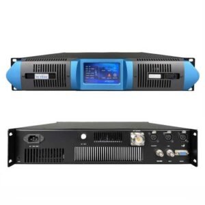
At RS, our transmitters from 50W upward include remote monitoring capability compatible with IP networks. This lets you build completely remote-managed sites with IP STL.
Practical Implementation
Test your IP connection thoroughly before committing. Run ping tests for latency. Check bandwidth consistency over days or weeks. If using point-to-point radio, verify link reliability in various weather conditions.
Configure quality of service (QoS) on network equipment to prioritize audio traffic. This prevents other data use from interrupting your broadcast.
Implement network monitoring to alert you if connection degrades. Simple ping monitoring or more sophisticated network management systems help you address problems proactively.
Document all network settings and configurations. Remote sites need clear documentation so anyone can troubleshoot if the primary engineer is unavailable.
Solution 2: Licensed Microwave STL with Professional FM Transmitter
%(Microwave STL)Licensed microwave STL for FM broadcasting
When Microwave STL Is the Right Choice
Maybe you need broadcast-grade reliability but lack fiber or reliable internet between studio and transmitter. Or your transmitter site is 10-50 km from the studio with good line-of-sight. Licensed microwave STL provides professional-quality dedicated link that’s been the broadcast standard for decades.
This solution works best for established stations with regulatory compliance requirements, communities where fiber isn’t available, and scenarios where link reliability matters more than initial cost. Government emergency broadcasting, professional community stations, and established religious broadcasters commonly use microwave STL.
Microwave STL Technology
Licensed microwave STL operates in dedicated frequency bands (typically 6 GHz, 7 GHz, 11 GHz, 13 GHz, 18 GHz, or 23 GHz depending on region and licensing). These bands are licensed specifically for broadcast studio-transmitter links, which means interference protection from other services.
The system uses parabolic dish antennas at both studio and transmitter site pointed at each other. In good line-of-sight conditions, microwave links reliably span 20-60 km. Some installations reach further with optimal conditions and larger antennas.
Audio quality equals or exceeds analog or digital wireline connections. Digital microwave systems provide uncompressed or lightly compressed audio with specifications matching professional studio equipment.
Advantages of Microwave STL
Reliability is the primary advantage. Licensed microwave links operate in protected spectrum with minimal interference. Weather affects performance less than might be expected—rain fade is the main concern at higher frequencies, but proper link budget design accounts for this.
Independence from third-party services means you control your own link. No dependency on internet service providers or telecommunications companies. No monthly recurring costs beyond initial licensing fees. For long-term installations, this saves money compared to leased circuits.
Low latency—microseconds through the air—makes microwave ideal for live programming where timing matters. No perceptible delay exists between studio and transmitter.
Predictable performance comes from dedicated spectrum and fixed frequency operation. The link either works correctly or it doesn’t—no gradual degradation or sharing with other users.
Technical Requirements
Line-of-sight is essential. The microwave path must be clear of obstructions. Even partial blockage significantly reduces reliability. Professional path surveys use topographic maps and software to verify line-of-sight accounting for Earth curvature and Fresnel zone clearance.
Frequency coordination and licensing is required in most countries. The telecommunications authority assigns specific frequencies to avoid interference with other microwave users. This process takes time—weeks to months depending on region.
Installation requires precision. Antenna alignment must be accurate to fractions of a degree. Professional installers use specialized tools to align antennas and optimize signal strength.
Maintenance is minimal once installed. Antennas might need realignment after extreme weather or building movement. Equipment inside requires standard maintenance like any broadcast gear.
System Components
A complete microwave STL system includes:
Studio Side:
- Microwave transmitter unit
- Parabolic antenna (size depends on frequency and distance)
- Antenna mounting hardware and mast
- Lightning protection and grounding
- Audio interface equipment
Transmitter Site:
- Microwave receiver unit
- Parabolic antenna
- Antenna mounting
- Lightning protection
- Audio connection to FM transmitter
Transmitter Pairing
Combine microwave STL with professional FM transmitters designed for continuous operation. The transmitter should include monitoring outputs for integration with microwave link status. Some installations use automatic failover to backup audio source if microwave link fails.
Higher reliability transmitters match the reliability investment of microwave STL. A professional 300W or 500W transmitter with robust protection systems complements microwave link for critical broadcast applications.
Cost Considerations
Microwave STL has higher initial cost than IP solutions. Equipment, licensing, and professional installation require significant investment. However, no ongoing monthly costs exist after installation (except possible license renewal fees).
Calculate total cost of ownership over 5-10 years. Monthly internet or circuit costs can exceed microwave investment over time. For permanent installations with long-term operation plans, microwave often costs less overall.
Implementation Best Practices
Complete professional path survey before purchasing equipment. This identifies any obstacles and determines required antenna sizes and transmitter power for reliable link.
Budget for professional installation. Microwave alignment requires expertise and specialized equipment. Poor installation wastes equipment investment.
Include lightning protection in design. Both sites need proper grounding and surge protection. Mountaintop sites especially experience significant lightning exposure.
Plan backup power for both ends of the link. If the transmitter site has backup power but studio doesn’t, link fails when studio power fails. Both ends need equal reliability.
Document link specifications including frequencies, antenna types, power levels, and alignment procedures. This information is essential for maintenance and troubleshooting years later.
Solution 3: Satellite STL with Automated FM Transmitter System
%(Satellite STL)Satellite STL for remote FM transmitter sites
When Satellite STL Becomes Necessary
Maybe your transmitter site is truly remote—mountain locations beyond line-of-sight from your studio, island stations, or rural areas without internet infrastructure. Or you need to reach multiple transmitter sites across wide geographic area. When terrestrial links don’t work, satellite STL provides connectivity anywhere with clear sky view.
I’ve worked with customers operating transmitters in locations where no other STL option exists. Mountain peaks surrounded by higher terrain that blocks microwave. Islands without subsea fiber. Rural transmitters serving agricultural communities hours from urban infrastructure. These scenarios require satellite.
Satellite STL Technology
Broadcast satellite STL uses commercial satellite services—either dedicated broadcast satellites or general communications satellites. The studio uplinks audio to satellite, which rebroadcasts it to coverage area. Small dish at transmitter site receives the signal.
Two main approaches exist:
Dedicated Broadcast Satellite: Some regions have satellites specifically for broadcast distribution. These provide high quality audio with minimal latency. Multiple stations can share the satellite capacity. This is common in North America and Europe.
VSAT (Very Small Aperture Terminal): Uses general communications satellites with IP data service. Similar to satellite internet but optimized for broadcast. Your audio travels as IP streams through the satellite network.
Advantages and Limitations
The primary advantage is geographic reach. Satellite works almost anywhere on Earth with clear sky view. This makes otherwise impossible broadcasts feasible.
Reliability is generally good—weather affects satellite less than you might expect. Heavy rain or snow can cause signal degradation, but link margins account for typical weather.
Multi-site distribution is efficient. One uplink can feed multiple transmitter sites. For networks operating several transmitters, satellite is cost-effective compared to individual terrestrial links to each site.
However, limitations are significant:
Cost is High: Satellite capacity isn’t cheap. Monthly service fees can be substantial, especially for high-quality audio or multiple channels. Initial equipment cost is also considerable.
Latency Exists: Geostationary satellites orbit 36,000 km above Earth. Round-trip signal delay is approximately 240 ms minimum. This affects live interactive programming and makes satellite unsuitable for two-way communication without noticeable delay.
Bandwidth is Expensive: High bitrate audio consumes bandwidth that translates to higher costs. Most satellite STL uses moderate compression to reduce bandwidth costs while maintaining acceptable quality.
Weather Sensitivity at High Frequencies: Ka-band and higher frequencies experience more rain fade than lower frequencies. Link design must include sufficient margin for weather.
System Configuration
A satellite STL system includes:
Studio Uplink:
- Satellite modem or encoder
- Uplink antenna (0.75m to 1.8m dish typical)
- High-power amplifier (SSPA)
- Feed system and LNB
- Control and monitoring equipment
Transmitter Site Downlink:
- Satellite receiver or decoder
- Receive antenna (0.75m to 1.2m dish typical)
- LNB and feed system
- Audio output to FM transmitter
Service Subscription:
- Monthly satellite capacity fee
- Bandwidth allocation
- Possible setup and coordination fees
Critical Transmitter Features
Pair satellite STL with FM transmitters that include local audio backup capability. Because satellite links can fail (equipment problems, weather outages, service interruptions), the transmitter site needs alternative audio source.
The transmitter should automatically detect loss of satellite audio and switch to local backup—perhaps automated playout computer or simple audio loop. When satellite returns, automatic switchback to live audio. This requires transmitter with audio sensing and automatic failover.
At RS, we help customers design systems with automatic audio failover for satellite-fed remote sites. The transmitter monitors audio presence and switches sources without manual intervention.
Practical Implementation
Antenna Pointing is Critical: Satellite dishes must be precisely aimed at the satellite. Professional installers use satellite meters and spectrum analyzers to optimize pointing. Even slight misalignment reduces signal quality significantly.
Coordinate with Satellite Provider: Before ordering equipment, confirm satellite service availability in your region and verify coverage includes your transmitter site. Not all satellites cover all areas.
Plan for Weather Margins: Design link budget with sufficient margin for rain and snow. The satellite provider can help calculate required margin based on your location and climate.
Implement Backup Audio: Essential for satellite systems. The transmitter site needs local automated audio source (computer with scheduled programming, audio loop device, or backup audio processor) that activates when satellite signal fails.
Consider Hybrid Approach: For critical broadcasts, satellite might be the primary link with cellular or other backup. Or satellite as backup for terrestrial links. Hybrid designs improve overall reliability.
Monitor Link Quality: Install monitoring equipment that tracks satellite signal levels and alerts you to degradation before complete failure. This allows proactive maintenance.
Energy Considerations: Satellite equipment at transmitter site consumes power continuously. For solar or battery-powered sites, this adds to energy budget. Calculate total power requirement including satellite receiver and transmitter.
Solution 4: Fiber Optic or Telco Circuit STL with High-Power Transmitter
%(Fiber STL)Fiber optic STL for FM transmitter high power
When Fiber or Telco Circuits Work Best
Maybe your transmitter site is on a high building in urban area, or a tower site near telecommunications infrastructure, or a hilltop with fiber access. Where fiber optic cable reaches or telecommunications carriers offer dedicated circuits (T1, E1, or similar), these provide premium quality STL with maximum reliability.
This solution suits professional installations where audio quality cannot be compromised, stations operating multiple program channels simultaneously, and facilities where the infrastructure investment justifies fiber installation. Urban community stations, campus stations in connected areas, and commercial or government broadcasters commonly use fiber STL.
Fiber and Telco Circuit Advantages
Unlimited Bandwidth: Fiber carries essentially unlimited audio channels with uncompressed quality. You can transmit stereo audio plus multiple subchannels, telemetry, remote control data, video monitoring, and more—all on one fiber strand.
Zero RF Interference: Fiber is immune to radio interference, electromagnetic interference, and lightning-induced problems that affect wireless systems. Reliability is exceptional in electrically noisy environments.
No Latency: Signal travels at light speed through fiber with negligible delay. Perfect for live programming requiring precise timing.
Distance Capability: Single mode fiber reaches 40 km or more without repeaters. With proper equipment, much longer distances are possible. This covers virtually any studio-to-transmitter distance.
Future Proof: Fiber infrastructure supports technology upgrades indefinitely. Change equipment at both ends to increase capacity or add features without replacing the fiber.
Security: Physical fiber is difficult to tap without detection. For broadcasts where content security matters, fiber provides physical layer protection.
Technical Options
Dark Fiber: If you control fiber strands between studio and transmitter, use dedicated broadcast fiber equipment. This provides maximum flexibility and capacity but requires fiber ownership or long-term lease.
Lit Service: Telecommunications carriers offer managed fiber circuits where they provide and maintain all equipment. You simply connect your audio at both ends. Higher monthly cost but minimal technical complexity.
Telco Circuits (T1/E1): Digital circuits provided by phone companies. Lower capacity than fiber but adequate for audio STL. More common in areas where fiber isn’t available but telco infrastructure exists.
System Architecture
A fiber STL system includes:
Studio Side:
- Fiber optic transmitter or telco interface
- Audio codec or direct AES/EBU interface
- Network or control equipment
- Fiber patch panel and protection
Fiber or Circuit:
- Fiber optic cable (owned or leased)
- Or telco T1/E1 circuit
- Intermediate repeaters if needed for long distances
Transmitter Site:
- Fiber receiver or telco interface
- Audio decoding equipment
- FM transmitter interface
- Monitoring and control systems
Transmitter Selection
Fiber STL typically pairs with higher power professional transmitters—500W to 5000W—for serious broadcast operations. These stations make significant infrastructure investment and need transmitter capability to match.
The transmitter should include professional remote control interface compatible with studio automation systems. Full remote monitoring of all parameters via fiber-carried data connection. Capability to control transmitter completely from studio.
Integration with broadcast automation systems allows centralized control of transmitter along with studio equipment and satellite receivers. The entire facility operates as integrated system.
Cost Considerations
Fiber has high initial cost if installation is required. Construction costs for fiber trenching, conduit, and installation vary dramatically based on distance and terrain. Urban areas with existing underground infrastructure might charge per meter for fiber installation. Rural areas might require significant construction.
If fiber already exists (building interconnect, campus fiber network, telecommunications infrastructure), connection cost is much lower. You pay for fiber interface equipment and circuit fees if applicable.
Monthly costs depend on whether you own fiber or lease circuits. Dark fiber might have annual lease fees. Lit services and telco circuits have monthly recurring charges that can be substantial.
Calculate return on investment based on service life. Fiber infrastructure lasts 20+ years. If you operate a station for decades, fiber investment amortizes over time compared to cumulative monthly costs of other solutions.
Implementation Approach
Survey Infrastructure First: Before planning fiber STL, determine what infrastructure exists. Does fiber currently reach your transmitter site? Would telecommunications carrier install fiber? What’s the cost?
Evaluate Ownership vs. Lease: If fiber installation cost is significant, compare owning fiber versus leasing circuits from carrier. Own fiber has higher initial cost but lower long-term cost. Leased circuits have lower initial cost but ongoing monthly fees.
Plan for Protection: Fiber cables are vulnerable to construction damage, rodent damage, and accidental cuts. Where possible, route fiber along protected paths. Some installations use dual diverse fiber routes for redundancy.
Include Backup: Even fiber fails occasionally. Consider backup STL option—microwave, IP, or satellite—to maintain broadcast during fiber repairs. Automatic failover to backup when fiber link fails.
Coordinate with IT Department: For campus and organizational stations, fiber STL might integrate with existing fiber networks. Coordinate with network engineers to ensure proper implementation and avoid conflicts with other network uses.
Test Thoroughly: Fiber systems should provide near-perfect quality. Test audio quality, monitor latency, verify remote control functionality, and stress test before relying on the system for broadcast.
Solution 5: Hybrid STL with Automatic Redundancy
%(Hybrid redundant STL)Hybrid redundant STL system for FM broadcasting
Why Hybrid Redundancy Matters
Maybe you operate a station where broadcast interruption is unacceptable—emergency broadcasting, commercial stations with advertising commitments, or community stations serving as primary information source. Single STL technology creates single point of failure. When that link fails, you’re off air until repair. Hybrid STL combines multiple technologies with automatic failover for maximum reliability.
I’ve designed systems for government emergency broadcasters that must stay on air during disasters, community stations that can’t afford extended downtime, and commercial operations where off-air time costs revenue. These applications require redundancy at system design level, not just backup equipment.
Hybrid STL Concepts
Hybrid STL uses two or more different technologies simultaneously. One technology operates as primary link carrying the live broadcast. Secondary link operates standby or monitors constantly. When primary fails, automatic switchover activates secondary within seconds. When primary recovers, system switches back.
The key principle is technology diversity. Don’t use two identical links—if one fails from a specific cause, the identical backup likely fails the same way. Use fundamentally different technologies so single point failures affect only one link.
Common Hybrid Combinations
Licensed Microwave + IP STL: Primary link is professional microwave for best quality and reliability. Backup is IP over commercial internet or cellular. The two systems share no common infrastructure. Microwave path failure doesn’t affect IP connection. Internet outage doesn’t affect microwave.
Fiber + Wireless IP: Where fiber exists, it provides primary link with excellent quality. Backup is wireless IP radio or cellular modem. Fiber cut doesn’t affect wireless. RF interference doesn’t affect fiber.
IP Microwave + Cellular: For point-to-point IP radio installations, cellular backup provides alternative path. Weather affecting microwave radio doesn’t affect cellular. Cellular network congestion doesn’t affect microwave.
Microwave + Satellite: Professional microwave provides primary link. Satellite backup activates if microwave fails. Two completely independent technologies with different failure modes.
Dual Path IP with Link Bonding: Advanced approach uses multiple IP connections (fiber + cable modem + cellular) with smart bonding technology that combines bandwidth and provides seamless failover. Any single connection can fail without interrupting audio.
System Architecture
Hybrid STL requires intelligent switching:
Studio Equipment:
- Primary STL encoder/transmitter
- Secondary STL encoder/transmitter
- Failover controller or audio router
- Monitoring system that detects link failures
Multiple Transmission Paths:
- Primary link infrastructure
- Secondary link infrastructure (different technology)
- Each with independent power and routing
Transmitter Site:
- Primary STL receiver/decoder
- Secondary STL receiver/decoder
- Automatic switcher or codec with dual input
- FM transmitter with reliable audio interface
- Silence detector for ultimate failover to local backup
Switching Logic
Automatic failover requires intelligent detection of link failure and quick switching. Modern STL equipment includes this functionality:
Audio Loss Detection: System continuously monitors received audio for silence or abnormal conditions. If audio fails for specified time (typically 3-10 seconds), failover triggers.
Link Status Monitoring: Some equipment monitors connection status at network level. IP connectivity loss, packet loss exceeding threshold, or latency increase can trigger failover before audio completely fails.
Manual Override: Operators should be able to force selection of specific link for maintenance or testing.
Automatic Restoration: When primary link recovers, system should return to primary automatically or alert operator to switch back manually depending on configuration.
Critical Implementation Details
Time Synchronization: Both links should be synchronized so seamless switching occurs without noticeable gap. Some systems buffer audio and cross-fade between sources during switch.
Equal Quality: Secondary link should provide quality equal to or close to primary. If backup quality is noticeably worse, listeners detect every failover event.
Power Independence: Each link needs independent power at both ends. If both links share power source, power failure defeats redundancy. Battery backup or dual power sources help.
Testing Failover: Regularly test automatic switching by deliberately failing primary link. Verify secondary activates correctly and return to primary works. Many systems fail when actually needed because failover was never tested.
Monitoring and Alerts: System should alert operators immediately when failover occurs. You need to know primary link failed so you can troubleshoot while secondary maintains broadcast.
Transmitter Compatibility
Hybrid STL pairs with transmitters that accept multiple audio inputs with automatic sensing or external control. The transmitter or external audio router must quickly switch between sources without audio gap.
Some professional transmitters include dual audio inputs with automatic failover built-in. This simplifies system design. Otherwise, external audio switching equipment handles the failover.
The transmitter should also integrate with monitoring systems that track which STL linkis active and alert when failures occur. Complete system monitoring provides visibility into the entire broadcast chain.
Cost and Value
Hybrid systems cost more than single-link solutions. You’re essentially paying for two complete STL systems plus switching equipment. However, for critical applications, the reliability justifies the cost.
Calculate downtime cost. How much does broadcast interruption cost in lost audience, damaged reputation, or missed revenue? For many stations, even short outages cost more than redundant system investment.
Consider staged implementation. Start with primary link and basic backup. Upgrade to sophisticated hybrid system as budget allows. The transmitter site infrastructure should accommodate future redundancy even if not implemented initially.
Real-World Scenarios
Emergency broadcast stations serving as primary alert system during disasters need hybrid redundancy. When hurricanes, earthquakes, or other emergencies occur, the broadcast must continue despite infrastructure damage.
Commercial stations with significant advertising revenue can’t afford extended outages. Every hour off air loses revenue and damages advertiser relationships. Hybrid STL prevents these losses.
Community stations serving as primary information source for rural or underserved areas have social responsibility to maintain service. Hybrid systems ensure the community stays connected.
Religious broadcasters reaching congregations across wide areas use hybrid systems to maintain consistent service for worship and community programming.
Implementation Best Practices
Choose truly independent technologies. Don’t use two microwave links on different frequencies—both fail in same weather conditions. Don’t use two IP connections from same provider—provider outages affect both. Select fundamentally different approaches.
Design for graceful degradation. Primary might be high-bitrate uncompressed audio. Secondary could be moderate compression. If primary fails, broadcast continues with acceptable quality rather than silence.
Document failover behavior. Operators and technical staff need to understand exactly what happens during switching. Clear documentation prevents confusion during actual failures.
Establish monitoring procedures. Assign responsibility for responding to failover alerts. Define troubleshooting steps for common failure modes.
Budget for ongoing maintenance of both systems. Both links need regular testing and maintenance to ensure readiness when needed.
Solution 6: Transmitter-Site Automation with Local Audio Backup
%(Transmitter site automation)FM transmitter site automation and local backup
The Complete Remote Solution
Maybe you’ve planned excellent STL to your remote transmitter site but worry about that inevitable moment when even the best link fails. Or your site is so remote that accessing it during emergencies is impossible. Or you need truly unattended operation with absolute reliability. Transmitter-site automation with local audio backup creates the most robust remote site possible.
This approach acknowledges that no STL is perfect. Instead of only improving the link, you reduce dependency on the link. The transmitter site operates semi-independently with local intelligence and backup content. When STL fails, the site continues broadcasting using local resources until the link recovers.
How Site Automation Works
Traditional remote sites are completely dependent on STL. The transmitter receives audio from studio and broadcasts it. If STL fails, the transmitter has no audio source—the station goes silent. This creates pressure to maintain perfect STL reliability, which is expensive or impossible.
Site automation reverses this thinking. The transmitter site includes local audio generation capability. A computer, media player, or dedicated automation device stores programming content locally. Under normal operation, the transmitter broadcasts STL audio from the studio. When STL fails, automatic switching activates local backup content.
The switch can be simple—silence detector that switches to backup when studio audio stops. Or sophisticated—intelligent system that detects audio problems before complete failure and performs seamless transition to backup programming.
Local Backup Content Options
Several approaches provide local audio backup:
Emergency Loop: Simplest option is audio loop device that plays recorded announcement explaining temporary technical difficulty. This keeps station on air with clear message to listeners. The loop might include station identification and information about expected return to normal programming.
Scheduled Playout Computer: More sophisticated approach uses computer running broadcast automation software. The system stores days or weeks of programming—perhaps pre-recorded shows, music libraries, or evergreen content. When STL fails, the computer takes over with actual programming rather than just announcement loop.
Syndicated Content Receiver: Some stations subscribe to satellite-delivered syndicated programming. The receiver stores programming and becomes backup source when STL fails. This provides quality content automatically without manual preparation.
Smart Playlist Systems: Dedicated devices designed for backup operation. They store music and programming, monitor incoming audio, and automatically switch to backup when needed. When studio audio returns, they switch back automatically.
Internet Stream Backup: Where internet connectivity exists at transmitter site separate from primary STL, internet stream of your station or compatible programming becomes backup source. The system monitors primary STL and switches to stream if needed.
Hybrid Local/Remote: Most sophisticated approach combines local automation with selective remote content. The local system handles routine programming like music between certain hours. Studio provides live shows and breaking information. Loss of STL reduces programming variety but doesn’t stop the broadcast.
Automatic Switching Technology
Reliable switching between STL and local backup requires proper detection and control:
Audio Presence Monitoring: System monitors STL audio for silence or very low levels. After specified duration (typically 5-10 seconds), switching activates. This prevents false switching on brief audio pauses but responds quickly enough to avoid extended silence.
Pilot Tone Detection: More sophisticated approach uses pilot tone—inaudible tone transmitted with STL audio. Loss of pilot tone indicates STL failure even if noise or interference creates audio-like signal. Prevents mistaken broadcasting of noise.
Network Status Monitoring: For IP STL, network connectivity monitoring provides early warning of link problems. System can switch to backup based on network status before audio completely fails.
Manual Override: Operators should be able to force local or remote audio source for testing and maintenance. Local control at transmitter site allows maintenance personnel to select sources directly if needed.
Automatic Restoration: When STL returns, the system should detect this and switch back to live audio. This might be automatic after verification of audio quality, or manual after operator confirmation.
Transmitter Requirements
Site automation requires transmitters with appropriate audio input configuration:
Multiple Audio Inputs: The transmitter needs at least two audio inputs—one for STL receiver, one for local backup source. Automatic or manual switching between inputs is essential.
Audio Failover Logic: Better transmitters include built-in audio sensing and automatic failover. They monitor the primary audio input and automatically switch to secondary if the primary fails. When primary recovers, they switch back.
Remote Monitoring: The transmitter should report which audio source is active. Operators need to know when the system has failed over to backup so they can investigate STL problems.
Reliable Operation: Since the site operates unattended, the transmitter must handle routine operation without intervention. Over-temperature protection, high SWR protection, and automatic recovery from faults are essential.
At RS, our transmitters from 50W upward include dual audio inputs with automatic sensing. This built-in capability simplifies site automation design. The transmitter continuously monitors both inputs and uses whichever has valid audio signal, prioritizing primary over backup.
Complete System Architecture
A fully automated remote site includes:
STL Receiver: Whatever technology you’ve chosen—IP, microwave, satellite, or fiber—receives audio from studio.
Local Backup Source: Computer, player, or automation device with stored programming content.
Audio Routing: Automatic switcher or transmitter with dual inputs handles audio source selection.
FM Transmitter: Professional transmitter with remote monitoring, dual audio inputs, and robust protection systems.
Site Monitoring: Environmental sensors, power monitoring, and status reporting equipment.
Remote Control: Network or dial-up access for transmitter control and monitoring.
Power Systems: Reliable power with battery backup or generator. For critical sites, redundant power sources.
Environmental Protection: Weatherproof equipment shelter, climate control, and environmental monitoring.
Power Management
Remote sites often have power challenges. Automation equipment adds to power consumption, which matters for solar or battery systems.
Calculate total site power requirement including transmitter, STL receiver, backup audio source, network equipment, and environmental control. For alternative energy sites, ensure solar array and battery capacity cover continuous operation including automation systems.
Implement power monitoring that alerts you to power problems before batteries deplete. Some systems automatically reduce transmitter power or shut down non-essential equipment to extend battery life during power outages.
Practical Implementation
Test Failover Regularly: Monthly or quarterly testing verifies automatic switching works correctly. Deliberately interrupt STL and confirm backup activates smoothly. Time how long the system takes to detect failure and switch.
Maintain Backup Content: Local backup content needs regular updates. Music libraries need refreshing. Announcements need updating. Programming should be recent and relevant, not years old.
Monitor Site Continuously: Automated sites need continuous remote monitoring. You should know immediately when failover occurs or when equipment reports faults. Monitoring systems should send alerts via email, SMS, or phone call.
Document Procedures: Write clear procedures for common scenarios—replacing backup content, troubleshooting STL problems, forcing audio source selection, etc. Documentation helps anyone maintain the site, not just the original installer.
Plan Access: Even automated sites need occasional physical access for maintenance. Arrange access methods—key codes, building security coordination, or designated personnel with site access—before problems occur.
Implement Security: Automated sites operating unattended need security. Physical security prevents unauthorized access and equipment theft. Cyber security protects network-connected equipment from hacking or disruption.
Value of Site Automation
The investment in site automation provides several benefits beyond just reliability:
Reduced Operational Pressure: When you know the site can operate independently during STL failures, you can troubleshoot problems without panic. No frantic midnight drives to restore broadcast because backup is already running.
Maintenance Flexibility: Site maintenance can happen during business hours without taking station off air. Local backup operates while you work on transmitter or STL equipment.
Storm Resilience: During severe weather when STL might fail and site access is impossible, local automation keeps station on air serving the community when information is most needed.
Cost Efficiency: Rather than investing in expensive STL redundancy, less expensive site automation provides different kind of reliability. Both approaches have value, but automation might be more economical for some applications.
Real-World Applications
Community stations serving emergency information during disasters use site automation. When storms damage STL infrastructure, the automated site continues broadcasting emergency information and station identification.
Religious broadcasters serving regular worship schedules use automation to ensure consistent service. When technical problems occur, the automated site broadcasts recorded services maintaining connection with congregation.
Campus stations operating primarily during academic terms use automation for break periods or low-listener hours. The automated site maintains broadcast presence with minimal operator involvement.
Rural stations covering vast areas use automation because transmitter sites are very remote. Site visits take hours, making automated operation essential for practical operation.
How to Choose the Right Solution for Your Remote Site
%(Choosing the right solution)Choosing the best FM transmitter remote site solution
Evaluation Framework
Selecting the optimal remote transmitter solution requires evaluating your specific situation across multiple factors. No single solution works for every application. Consider these key questions:
1. Site Characteristics
What is the transmitter site location and environment?
- Distance from studio (5 km, 20 km, 50 km+)
- Line-of-sight visibility from studio
- Terrain type (mountain, valley, urban, rural)
- Climate and weather extremes
- Access difficulty and frequency
- Available infrastructure (power, internet, telecommunications)
2. Coverage Requirements
What coverage area and transmitter power do you need?
- Coverage radius or area shape
- Terrain affecting propagation
- Population served
- Required signal strength
- Indoor versus outdoor coverage priority
- Mobile versus fixed reception
3. Reliability Needs
How critical is continuous operation?
- Can you tolerate brief outages?
- What’s the cost or impact of downtime?
- Are there regulatory uptime requirements?
- Do you serve emergency information?
- What maintenance response time is acceptable?
4. Audio Quality
What audio quality standards apply?
- Music programming requiring high fidelity
- Speech programming with moderate quality acceptable
- Stereo versus mono requirements
- Latency tolerance for live programming
- Multiple program channels needed
5. Technical Capabilities
What technical resources and expertise do you have?
- In-house technical staff or consultants
- Familiarity with different technologies
- Installation capabilities
- Ongoing maintenance capacity
- Troubleshooting expertise
6. Budget Reality
What’s your realistic budget for complete system?
- Initial equipment purchase
- Installation and setup costs
- Ongoing monthly fees (circuits, internet, satellite)
- Maintenance and repair budget
- Long-term operational costs
- Upgrade and expansion plans
Decision Matrix
Based on these factors, here’s guidance for matching solutions to scenarios:
Short Distance with Line-of-Sight (under 10 km):
- Primary Choice: IP-based STL using point-to-point wireless or internet
- Alternative: Licensed microwave if long-term operation justifies investment
- Backup: Local audio automation at transmitter site
Medium Distance with Good Line-of-Sight (10-40 km):
- Primary Choice: Licensed microwave STL for professional reliability
- Alternative: IP STL if reliable circuits or line-of-sight radio works
- Backup: Consider hybrid redundancy or local automation
Long Distance or No Line-of-Sight:
- Primary Choice: Fiber or telco circuits where available
- Alternative: Satellite STL for truly remote locations
- Backup: Local automation essential for very remote sites
Urban or Campus Settings with Infrastructure:
- Primary Choice: Fiber or existing network infrastructure
- Alternative: Short-range IP STL
- Backup: May not need extensive backup with reliable infrastructure
Critical Reliability Requirements:
- Primary Choice: Hybrid redundant STL with diverse technologies
- Alternative: Single excellent STL plus comprehensive local automation
- Backup: Multiple layers of backup including UPS, generator, local programming
Budget-Constrained Projects:
- Primary Choice: IP STL using existing internet or affordable equipment
- Alternative: Basic microwave if distance is short
- Backup: Simple audio loop backup rather than sophisticated automation
Very Remote or Difficult Access:
- Primary Choice: Satellite STL or any available connectivity
- Alternative: Combination of basic STL plus extensive local automation
- Backup: Solar power, satellite backup internet, comprehensive automation
Transmitter Power Matching
Match transmitter capability to your chosen STL solution:
Basic IP STL or Simple Equipment: Pair with economical 15-100W transmitters for community, campus, or local religious broadcasting.
Professional Microwave or Fiber STL: Pair with robust 100-500W transmitters for established community stations or regional coverage.
Redundant or Satellite STL: Pair with high-reliability transmitters 300W+ including full remote control and monitoring.
Highly Automated Sites: Pair with transmitters offering dual audio inputs, extensive protection systems, and proven reliability for unattended operation.
At RS, we help customers match transmitter specifications to their STL infrastructure and coverage requirements. Our transmitters from 7W to 10KW cover the full range from simple to sophisticated applications.
Common Mistakes to Avoid
Underestimating Backup Importance: Many projects focus on primary STL reliability but ignore backup. Even excellent STL systems fail occasionally. Budget for backup from the start.
Ignoring Power Requirements: STL equipment and automation systems consume power. For alternative energy sites, verify your power system handles all equipment, not just the transmitter.
Skipping Path Surveys: For microwave or line-of-sight IP links, proper path survey prevents expensive mistakes. Don’t assume line-of-sight without verification.
Choosing Based Only on Initial Cost: Lowest-cost equipment often creates highest long-term costs through failures, maintenance, and eventually replacement. Consider total cost of ownership.
Overlooking Licensing and Regulations: Some STL technologies require licenses or authorizations. Factor these requirements and costs into planning.
Inadequate Testing: Many systems work fine in bench tests but fail in real-world conditions. Test thoroughly under actual operating conditions before depending on the system.
Poor Documentation: Remote sites need excellent documentation. Future maintainers must understand system design and operation. Invest time in creating clear documentation.
Summary: Building Reliable Remote Transmitter Systems
%(Remote transmitter system)Complete remote FM transmitter system solution
Remote transmitter sites provide excellent broadcast coverage but create technical challenges that require careful system design. The Studio-to-Transmitter Link determines whether your station operates reliably or struggles with outages and quality problems.
Six main solution approaches each suit different scenarios. IP-based STL offers flexibility and reasonable cost where network connectivity exists. Licensed microwave provides broadcast-grade reliability with dedicated spectrum. Satellite STL reaches locations where nothing else works. Fiber and telco circuits deliver maximum quality for connected sites. Hybrid redundancy combines multiple technologies for critical applications. Site automation reduces dependency on perfect STL with local backup capability.
The best solution for your situation depends on site characteristics, coverage requirements, reliability needs, audio quality standards, technical capabilities, and realistic budget. Most professional installations combine primary STL technology with backup systems—either redundant links or local automation—to ensure continuous operation.
Select transmitters matched to your STL investment and reliability requirements. Basic STL works with economical transmitters for simple applications. Professional STL infrastructure deserves transmitters with comprehensive remote control, monitoring, and protection systems.
At RS, we work with customers worldwide to design complete remote transmitter solutions. Our engineering team helps evaluate site conditions, select appropriate STL technology, specify transmitter requirements, and design integrated systems that operate reliably in challenging conditions. We provide transmitters from 7W to 10KW with features supporting professional remote operation.
Whether you’re establishing campus radio on a water tower, community broadcasting from a mountain peak, religious programming from a remote tower, or emergency communications across rural regions, proper system design ensures your remote transmitter site operates reliably for years.
About RS (Risheng Electronics)
RS manufactures professional FM broadcast transmitters designed for remote site operation. Power ranges from 7W to 10KW with FCC and CE certificates, backed by 5-year warranty.
Remote Site Features:
- Dual audio inputs with automatic failover
- Complete remote monitoring and control
- Over-temperature and high SWR protection
- Low power consumption for alternative energy sites
- Weather-resistant construction
- Network-ready for IP integration
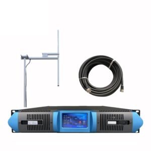
Complete Solutions:
We provide matched systems including transmitter, antenna, cable, and installation guidance. Our engineering team helps design STL systems and site automation for reliable remote operation.
Technical Support:
Lifetime support via WhatsApp engineering group. Remote troubleshooting, installation guidance, and system optimization assistance included with every transmitter.
Applications:
Remote transmitter sites for community radio, campus broadcasting, religious programming, emergency communications, and commercial operations worldwide.
Global Experience:
We’ve supported remote transmitter installations in mountainous regions, island locations, rural areas, and urban tower sites across 50+ countries including USA, Mexico, Philippines, Nigeria, Kenya, Ghana, Tanzania, and DR Congo.
Why Choose RS for Remote Sites:
Proven reliability in unmanned operation, comprehensive protection systems, remote control capability, energy-efficient design, and responsive technical support for troubleshooting from anywhere.
Need help designing your remote transmitter site? Our engineering team provides free consultation on STL selection, system architecture, power planning, and installation approach.
Visit https://fmradiotx.com/ for transmitter specifications, remote site planning guides, STL integration information, and technical resources.
WhatsApp Technical Support: Contact our engineering team for remote site consultation and system design assistance.