Top 10 Real-World Coverage Examples for 50W / 100W / 300W / 1000W FM Transmitters
I’m an RF engineer at RS, and I’ve helped hundreds of stations plan their coverage. Maybe the most common question I get is "how far will X watts really reach?" The answer is always "it depends"—on your antenna height, terrain, whether you’re in city or countryside, and what quality you need.
This article shows 10 real-world coverage scenarios I’ve worked on or studied. These aren’t theoretical calculations—they’re based on actual stations and field measurements. Use these examples to understand what different power levels actually achieve under specific conditions.
Understanding FM Coverage: 4 Key Factors Before the Examples
Power Alone Doesn’t Determine Coverage
Maybe you think buying 1000W transmitter automatically gives you huge coverage. But I’ve seen 1000W stations barely covering 20 km due to poor antenna placement, while 100W stations with good tower height reach 25 km. Coverage depends on the complete system, not just transmitter power.
The 4 Critical Factors
1. Effective Radiated Power (ERP):
This combines transmitter power, antenna gain, and cable loss. A 100W transmitter with 3 dB gain antenna and 1 dB cable loss produces about 140W ERP. ERP determines actual radiated power, not the transmitter rating alone.
2. Antenna Height:
Higher antenna sees over obstacles and terrain features. Doubling antenna height from 20m to 40m might increase coverage radius 40-50%. Height is often more valuable than power.
3. Terrain Type:
Flat open land lets signals travel far. Hills create shadow zones. Mountains block signals completely. Dense forest absorbs signals. Urban buildings cause reflection and absorption.
4. Area Type (Urban vs Rural):
Rural areas have few obstacles—signals propagate efficiently. Urban areas have concrete buildings, metal structures, and electrical interference that reduce effective range significantly.
The Distance-Power Relationship
Here’s the fundamental rule: To double your coverage distance, you need roughly 4 times the power (assuming everything else stays constant).
Examples:
- 25W reaches 5 km → 100W reaches 10 km (4× power = 2× distance)
- 100W reaches 15 km → 400W reaches 30 km (4× power = 2× distance)
- 250W reaches 20 km → 1000W reaches 40 km (4× power = 2× distance)
This explains why jumping from 100W to 1000W (10× power) only increases range about 3× (not 10×). Physics makes coverage expansion expensive.
Coverage Quality Matters
When I say "coverage," I mean different things:
- Strong signal coverage: Perfect reception on any radio, indoor and outdoor
- Good signal coverage: Clear car radio reception, works on decent portables
- Fringe coverage: Audible with good radio and outdoor antenna, inconsistent quality
The examples below describe practical usable coverage—where most listeners get clear reception on car radios and portable radios outdoors.
Example 1: 50W Community Station in Flat Rural Area
Station Profile: Community radio serving farming villages in Tanzania
System Setup:
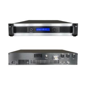
- Transmitter power: 50W ($488)
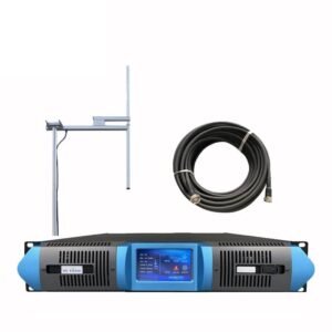
- Antenna: 2-bay circularly polarized at 25m height
- Antenna gain: 3 dB
- Cable loss: 1 dB
- ERP: Approximately 70W
- Terrain: Flat agricultural land, scattered trees
- Environment: Rural villages, light construction buildings
Coverage Results:
| Reception Type | Range / Quality |
|---|---|
| Strong signal (outdoor/car) | 0–4 km radius;Excellent, full stereo |
| Good signal (portable/indoor light) | 4–7 km radius;Clear, reliable |
| Fringe coverage (good radio) | 7–10 km radius;Acceptable, occasional fade |
Real-World Performance:
The station reaches 6 villages within 6 km radius with reliable signal. Farmers working outdoors receive clearly throughout the area. Indoor reception works well in light construction homes (wood, light metal roofing). Car radios pick up strong signal on all roads within 8 km.
Beyond 8 km, signal becomes inconsistent depending on specific location. The flat terrain helps—no major obstacles blocking signal propagation.
Who This Suits:
- Village radio serving 5,000-15,000 people in agricultural area
- Multiple small communities within 5-7 km radius
- Primarily outdoor/mobile listening
- Budget-conscious community broadcasting
Cost Analysis:
- Initial investment: $488 (transmitter) + $150 (antenna) + $100 (cable) = $738
- Monthly electricity: 150W × 24h × 30 days × $0.15/kWh = $16
- Sustainable for stations with minimal budget
Example 2: 50W Campus Radio in Small University
Station Profile: University radio station in Kenya serving campus and nearby town
System Setup:
- Transmitter power: 50W ($488)
- Antenna: Single dipole at 20m on campus building
- Antenna gain: 2 dB
- Cable loss: 0.5 dB
- ERP: Approximately 60W
- Terrain: Gently rolling, urban edge environment
- Environment: Campus buildings (concrete), surrounding residential neighborhood
Coverage Results:
| Area Type | Range / Reception Quality |
|---|---|
| Campus core (concrete buildings) | 0–2 km;Good indoor, excellent outdoor |
| Campus perimeter residential | 2–4 km;Clear in cars, fair indoors |
| Nearby town areas | 4–6 km;Outdoor/car reception, weak indoor |
Real-World Performance:
Indoor reception in campus dormitories and buildings works acceptably but not perfectly—concrete construction absorbs signal. Students outdoors on campus receive excellent signal. Car reception is strong throughout campus and surrounding 3 km radius.
The nearby town (3-4 km away) receives the station on car radios clearly. Indoor reception in town is inconsistent—works in some locations but not others.
Challenge: Campus buildings create signal shadows. Some dormitories on far side of metal-roofed structures receive weak signal indoors. Antenna positioning on campus building rooftop helps but doesn’t solve all shadow zones.
Who This Suits:
- University/college 2,000-10,000 students
- Campus up to 3 km across
- Student housing within 4 km
- Primary listening in cars, outdoor, and some indoor areas
Practical Notes:
If indoor dorm reception is critical, consider 100W upgrade for better building penetration. But for typical campus radio where students listen on portable radios outdoors or in cars, 50W works fine.
Example 3: 100W Small Town Station in Rolling Hills
Station Profile: Community station in Rwanda serving town and surrounding villages
System Setup:
- Transmitter power: 100W ($650)
- Antenna: 4-bay professional antenna at 30m tower
- Antenna gain: 6 dB (4× power gain)
- Cable loss: 2 dB
- ERP: Approximately 300W
- Terrain: Rolling hills, valleys, mixed elevation
- Environment: Town center (moderate density) plus rural villages
Coverage Results:
| Direction / Terrain | Range / Notes |
|---|---|
| Downhill / valley direction | 12–15 km;Strong signal follows terrain |
| Level terrain | 8–12 km;Consistent coverage |
| Uphill / ridge direction | 5–8 km;Terrain blocks signal |
| Town center indoor | 0–5 km;Good reception most buildings |
Real-World Performance:
Coverage is highly directional due to hills. Villages in valley below transmitter site receive strong signal 12-15 km away. Villages on same elevation get good coverage 8-10 km radius. Villages over ridge from transmitter struggle to receive signal beyond 5 km.
Town center (where transmitter is located) gets excellent coverage. Indoor reception works reliably in most buildings within 6 km. Car reception is solid throughout the 10 km radius except areas behind significant hills.
Solution Implemented: Station added 15W relay transmitter ($249) on far ridge to serve 3 villages in shadow zone. Total investment $650 + $249 = $899 provides more complete coverage than single 300W transmitter would achieve.
Who This Suits:
- Town of 10,000-25,000 population
- Multiple villages within 10 km
- Hilly terrain requiring strategic antenna placement
- Mixed indoor/outdoor listening
Key Lesson: In hilly terrain, 100W with good tower height (30m) plus relay transmitter often works better than single high-power transmitter. The physics of line-of-sight matters more than power when terrain creates obstacles.
Example 4: 100W Rural Station on Mountaintop Site
Station Profile: Religious broadcaster in Uganda using natural height advantage
System Setup:
- Transmitter power: 100W ($650)
- Antenna: 2-bay at 20m tower on mountain site
- Site elevation: 1,400m transmitter site, covering 900-1,000m elevation valley
- Antenna gain: 3 dB
- Cable loss: 1.5 dB (longer run from transmitter building to tower)
- ERP: Approximately 120W
- Effective height: 400-500m above coverage area
- Terrain: Looking down into agricultural valley
- Environment: Rural villages and farmland
Coverage Results:
| Coverage Zone | Distance / Reception |
|---|---|
| Primary valley coverage | 15–25 km radius;Excellent signal throughout |
| Secondary valley areas | 25–35 km radius;Good mobile reception |
| Distant villages | 35–45 km radius;Fringe coverage possible |
Real-World Performance:
The massive height advantage makes 100W perform like 500W+ on flat ground. Signal radiates down into valley with minimal obstacles. Villages 20 km away receive signal as if transmitter was 5 km away on level ground.
Coverage extends 25 km radius with reliable car and outdoor reception. Some locations 30-40 km away can receive the station on good radios due to line-of-sight from elevated site.
Indoor reception works surprisingly well throughout the valley—the strong signal from elevation above penetrates buildings better than same power at ground level.
Cost-Performance Analysis:
Option A (chosen): 100W on mountain site
- Equipment: $650 transmitter + $200 antenna + $100 cable = $950
- Site access: Challenging 4×4 road, requires careful logistics
- Coverage: 25 km+ effective radius
Option B (not chosen): 500W on valley floor
- Equipment: $1,560 transmitter + $500 antenna = $2,060
- Site access: Easy valley floor location
- Coverage: 15-18 km effective radius (worse than Option A)
The mountain site provides superior coverage at much lower equipment cost, despite logistical challenges.
Who This Suits:
- Stations with access to elevated sites
- Regional coverage with community station budget
- Serving valley or lower-elevation areas from height
- Willing to manage challenging site access
Important Note: Mountain sites face challenges—difficult access for maintenance, exposure to weather, lightning risk, and potentially unreliable power. But for coverage, elevation is incredibly valuable.
Example 5: 300W District Center Station in Mixed Terrain
Station Profile: Commercial station in Tanzania serving district town and surrounding area
System Setup:
- Transmitter power: 300W ($1,339)
- Antenna: 4-bay circularly polarized at 40m tower
- Antenna gain: 6 dB
- Cable loss: 2 dB
- ERP: Approximately 900W
- Terrain: Town on slight elevation, surrounding mixed flat and rolling terrain
- Environment: Urban town center (15,000 population) plus rural surroundings
Coverage Results:
| Coverage Type | Range / Reception Quality |
|---|---|
| Primary coverage (strong signal) | 0–18 km;Excellent indoor/outdoor |
| Secondary coverage (good signal) | 18–30 km;Clear car/outdoor reception |
| Fringe coverage | 30–45 km;Good radios can receive |
Real-World Performance:
Town center gets powerful signal—excellent indoor reception in all buildings including concrete construction. Surrounding villages within 20 km receive strong signal with clear indoor reception in light construction and perfect car/outdoor reception.
Agricultural areas 20-30 km from transmitter get good coverage for outdoor work and vehicle listening. Some villages 35-40 km away can receive the station, though quality varies by specific location and terrain features.
The 40m tower height combined with 300W power provides professional-quality coverage throughout the district. Listeners compare signal favorably to national broadcasters.
Coverage by Population:
Estimated population coverage:
- Within 15 km (strong signal): 45,000 people
- Within 25 km (good signal): 85,000 people
- Within 35 km (fringe reception): 120,000+ people
Revenue Justification:
As commercial station, the investment analysis showed:
Monthly costs:
- Equipment loan payment: $140 (24-month financing)
- Electricity: $70 (650W consumption × 720h × $0.15)
- Site rental: $100
- Maintenance: $40
- Total: $350/month
Revenue potential:
Covering 85,000 people with quality signal supports $1,500-2,500/month advertising revenue in this market, making operations highly profitable.
Who This Suits:
- Commercial stations serving district or small city
- 50,000-150,000 population coverage area
- Mixed urban and rural environment
- Revenue-supported operations justifying higher investment
Example 6: 300W City Station in Dense Urban Environment

Station Profile: Youth station in Lagos, Nigeria serving city neighborhood
System Setup:
- Transmitter power: 300W ($1,339)
- Antenna: 2-bay at 35m on office building
- Antenna gain: 3 dB
- Cable loss: 2 dB
- ERP: Approximately 350W
- Terrain: Flat urban area
- Environment: Dense city—multi-story buildings, heavy traffic, high electrical noise
Coverage Results:
| Area Type | Distance / Reception |
|---|---|
| Line-of-sight areas | 0–8 km;Strong signal |
| Urban neighborhoods (blocked) | 5–12 km;Good car reception, variable indoor |
| City outskirts | 12–18 km;Acceptable mobile reception |
| Beyond city | 18–25 km;Fringe coverage where clear |
Real-World Performance:
Urban environment dramatically reduces effective range compared to rural areas. Buildings block and absorb signal. Concrete and steel construction creates shadow zones. Electrical interference from dense development raises noise floor.
Coverage within 8 km is generally strong—listeners receive well in cars and outdoor. Indoor reception varies greatly by building construction and location. Modern concrete buildings with metal framing receive poorly. Older construction with wood framing receives better.
Beyond 10 km, coverage becomes inconsistent. Some areas have clear signal where terrain is open. Other areas struggle due to building density and interference.
Comparing Same Power Different Environment:
This 300W urban station vs rural Example 5:
| Factor | Urban (Example 6) | Rural (Example 5) |
|---|---|---|
| Power/ERP | 300W / 350W ERP | 300W / 900W ERP |
| Strong coverage | 8 km radius | 18 km radius |
| Usable coverage | 12 km radius | 30 km radius |
| Population covered | 400,000 (dense) | 85,000 (sparse) |
The urban station covers far smaller geographic area but serves more people due to population density. Coverage quality is also more challenging to maintain in urban environment.
Solution Approaches:
Station considered several options:
Option A: Increase power to 1000W ($1,890)
- Would extend range 15-20 km with good signal
- But doesn’t solve shadow zones behind buildings
- Higher operating costs
Option B: Add fill-in transmitters (chosen)
- Keep 300W main transmitter
- Add two 50W fill-in transmitters ($488 each) in shadow zones
- Better overall coverage than single high-power site
- More flexible for city environment
Who This Suits:
- City/urban stations
- Dense population with challenging RF environment
- Stations where population density matters more than geographic range
- Operations requiring multiple-site strategies
Key Lesson: In cities, 1000W might cover only what 300W covers in rural areas. Urban broadcasting requires different strategies—height, multiple sites, and realistic expectations about building penetration.
Example 7: 1000W Regional Station on Good Tower
Station Profile: Established commercial broadcaster in Kenya serving regional area
System Setup:
- Transmitter power: 1000W ($1,890)
- Antenna: 4-bay high-gain circularly polarized at 60m tower
- Antenna gain: 6 dB
- Cable loss: 3 dB (longer cable run from transmitter room)
- ERP: Approximately 2,000W
- Terrain: Transmitter on 50m elevation rise, surrounding relatively flat
- Environment: Regional station covering multiple towns and rural areas
Coverage Results:
| Coverage Zone | Distance / Reception Quality |
|---|---|
| Primary strong signal | 0–25 km;Excellent all conditions |
| Secondary good signal | 25–45 km;Reliable car/outdoor |
| Tertiary acceptable | 45–65 km;Decent radios receive clearly |
| Fringe / distant | 65–85 km;Possible with excellent radio / outdoor |
Real-World Performance:
The combination of 1000W power and 60m height provides true regional coverage. Signal is professional-quality throughout 40 km radius—strong indoor reception even in concrete buildings, perfect mobile reception, works on cheap radios.
Secondary coverage extends 45-50 km with reliable service for car radios and outdoor listening. Villages and towns in this ring receive good signal quality, though indoor reception in heavy construction might be inconsistent.
Beyond 50 km, coverage exists but becomes variable. Some locations 60-70 km away receive clearly—particularly in flat directions with clear line-of-sight. Other areas at same distance struggle due to terrain or obstacles.
Reports of reception 80+ km away in specific favorable locations (elevated receivers, clear line-of-sight, good equipment). But planning shouldn’t rely on this distant fringe coverage.
Population Coverage Analysis:
Within 30 km (strong signal): 3 towns and 120,000 rural population
Within 50 km (good signal): 8 towns/villages and 280,000 people
Within 70 km (acceptable signal): Extended rural areas and 400,000+ total population
Comparing 1000W to Lower Power Options:
To understand what 1000W provides versus alternatives:
| Power | Coverage / Reach / Cost |
|---|---|
| 300W | Primary 18 km;Good 30 km;120,000 people;$1,339 |
| 500W | Primary 22 km;Good 38 km;180,000 people;$1,560 |
| 1000W | Primary 28 km;Good 50 km;280,000+ people;$1,890 |
The 1000W provides roughly 1.5× the coverage radius of 300W (not 3×, due to physics). But reaching that extra 40% audience requires more than doubling the transmitter investment.
Operating Cost Reality:
Monthly costs:
- Electricity: 2,000W × 24h × 30d × $0.15 = $216
- Tower rental: $200
- Maintenance fund: $80
- Technical staff: $150
- Total operating: $646/month
Regional coverage supports this through advertising revenue. The station generates $3,500-5,000/month from advertisers wanting regional reach, making operations profitable.
Who This Suits:
- Established commercial broadcasters
- Regional population 200,000-500,000
- Multiple towns/district coverage
- Revenue model supporting higher operating costs
- Competitive market requiring strong signal quality
Example 8: 1000W Station on Modest Tower in Hilly Region
Station Profile: Government broadcaster in Ethiopia with coverage challenges
System Setup:
- Transmitter power: 1000W ($1,890)
- Antenna: 2-bay at 25m pole
- Antenna gain: 3 dB
- Cable loss: 2 dB
- ERP: Approximately 1,200W
- Terrain: Hilly/mountainous region, transmitter in valley
- Environment: Town center in valley, need to reach communities on surrounding hillsides
Coverage Results:
| Direction | Distance / Quality |
|---|---|
| Line-of-sight (valley floor) | 15–20 km;Excellent signal |
| Over first ridge | 8–12 km;Fair to poor |
| High elevation villages | 5–15 km;Inconsistent, depends on line-of-sight |
| Distant valleys | Minimal;Cannot reach over intervening terrain |
Real-World Performance:
Despite 1000W power, coverage is disappointingly limited. Terrain creates massive shadow zones. Villages on hillsides facing transmitter receive well—even 15 km away if they have line-of-sight. Villages behind ridges struggle to receive signal even 8 km away.
The valley floor gets excellent coverage extending 18-20 km. But this serves limited population compared to hillside communities that are the actual target audience.
The Problem:
Power can’t overcome terrain obstacles. 1000W radiating into hillside is wasted—signal doesn’t bend over ridges. Meanwhile, communities in shadow zones receive nothing despite being geographically close.
Better Solution (Eventually Implemented):
After analyzing coverage problems:
Original approach:
- 1000W transmitter in valley: $1,890
- 25m tower: $1,500
- Coverage: ~40% of target population
- Total: $3,390 with poor results
Improved approach:
- Moved 1000W transmitter to mountain site with line-of-sight to most target areas
- Invested in better access road and facilities
- Added 100W fill-in transmitter in remaining shadow zone
- Coverage improved to ~85% of target population
- Total: $5,200 including site improvements, but actually effective
Key Lesson:
This example shows that power alone solves nothing if site selection is poor. Better to use 300W from optimal site than 1000W from poor location. In hilly terrain:
- Site selection matters more than power
- Height (absolute elevation) is crucial
- Multiple modest transmitters often work better than single high-power unit
- You can’t fix bad site selection by throwing more power at the problem
Who Should Learn From This:
- Stations in mountainous regions
- Anyone planning site before buying equipment
- Understanding that power is just one factor in coverage
- Budget for site development, not just equipment power
Example 9: 300W + High-Gain Antenna for Extended Rural Coverage
Station Profile: Community development broadcaster in Ghana serving large rural area
System Setup:
- Transmitter power: 300W ($1,339)
- Antenna: 8-bay high-gain directional at 50m tower
- Antenna gain: 9 dB (approximately 8× power gain)
- Cable loss: 2.5 dB
- ERP: Approximately 1,400W effective
- Terrain: Relatively flat agricultural region
- Environment: Scattered villages across wide rural area
- Coverage pattern: Directional toward primary service area
Coverage Results:
| Direction | Distance / Reception |
|---|---|
| Main beam direction | 25–35 km;Strong signal |
| Secondary coverage | 35–50 km;Good car/outdoor |
| Side / rear directions | 8–15 km;Acceptable but weaker |
| Null areas (antenna pattern) | Variable;Minimal coverage by design |
Real-World Performance:
The high-gain antenna focuses power toward the intended service area rather than radiating equally in all directions. This provides coverage of 45+ km radius in the main direction—similar to what 1000W omnidirectional antenna might achieve, but at much lower transmitter cost and operating expense.
Primary coverage area (25 villages northeast of transmitter) receives strong signal comparable to 1000W installation. The signal reaches 40-45 km with reliable quality for car and outdoor reception.
Directions not in main antenna beam receive less coverage—typically 10-15 km usable range. But these directions contain minimal population, so the coverage loss doesn’t matter.
System Comparison:
To achieve similar coverage in primary direction:
Option A (chosen): 300W + high-gain directional antenna
- Transmitter: $1,339
- Special 8-bay antenna: $650
- Tower work: $2,500 (50m professional tower)
- Total: $4,489
- Power consumption: 650W
- Coverage: 45 km main direction
Option B: 1000W + standard omnidirectional antenna
- Transmitter: $1,890
- Standard antenna: $500
- Tower work: $2,200 (shorter tower acceptable)
- Total: $4,590
- Power consumption: 2,000W
- Coverage: Similar 45 km but all directions
Option A costs slightly less initially but saves significantly on electricity—$70/month vs $216/month for Option B. Over 3 years, electricity savings equal $5,256—far more than any equipment cost difference.
When Directional High-Gain Makes Sense:
Geographic targeting: Service area in one primary direction (coastal stations, border region broadcasting)
Terrain advantage: Pointing antenna toward flat open area while back side faces terrain obstacles anyway
Competition avoidance: Reducing signal toward competitor’s strong area while maximizing coverage in your target zone
Operating cost priority: When electricity costs matter more than omnidirectional coverage
Important Consideration:
High-gain antenna creates lobes and nulls—strong coverage in some directions, weak in others. This works perfectly when geography and population distribution align with your coverage goals. But if you need equal coverage all directions, omnidirectional antenna with higher power is better choice.
Who This Suits:
- Rural regional stations with directional service needs
- Stations prioritizing coverage distance over omni coverage
- Operations focused on electricity cost efficiency
- Geographic situations favoring directional coverage
Example 10: Multi-Transmitter Network for Complete District Coverage
Station Profile: District administration broadcaster in Tanzania ensuring complete coverage
System Setup:
Main transmitter (district capital):
- Power: 300W ($1,339)
- Antenna: 4-bay at 40m
- ERP: ~900W
- Coverage: 25 km primary radius
Relay transmitter #1 (northern valley):
- Power: 100W ($650)
- Antenna: 2-bay at 30m
- ERP: ~120W
- Coverage: 15 km filling shadow zone
Relay transmitter #2 (southern ridge):
- Power: 100W ($650)
- Antenna: 2-bay at 25m
- ERP: ~100W
- Coverage: 12 km filling shadow zone
Total system cost: $1,339 + $650 +$650 = $2,639
Coverage results: 98% geographic coverage of district, complete population coverage
Coverage Results by Area:
| Coverage Area | Signal / Relay / Total Coverage |
|---|---|
| District capital region | Primary 25 km (300W main);No relay;Excellent throughout |
| Northern valley towns | Weak from main (blocked);15 km (100W relay);Good coverage |
| Southern ridge villages | Moderate from main;12 km (100W relay);Strong coverage |
| Central rural areas | Overlap from all sites;Multiple signals;Excellent redundancy |
Real-World Performance:
The main 300W transmitter provides strong coverage throughout the central district—capital city and surrounding 25 km. But geographic analysis showed two shadow zones where terrain blocked main signal.
Northern valley (population 18,000) received weak signal from main transmitter due to intervening ridge. Adding 100W relay on north side of ridge provides strong local signal serving this population.
Southern highland villages (population 12,000) could barely receive main signal. The 100W relay placed on accessible ridge serves these communities with clear signal.
Central areas between transmitters receive signals from multiple sites—provides redundancy if one transmitter experiences problems. Listeners automatically receive from strongest available signal.
Why Multiple Sites Work Better Than Single High Power:
Alternative considered: Single 1000W transmitter at main site
- Equipment: $1,890
- Would improve main coverage to ~30 km radius
- But shadow zones would still exist due to terrain
- Power can’t overcome line-of-sight obstacles
- Estimated 75-80% population coverage
Actual multi-site approach:
- Total equipment: $2,639
- Achieves 98% population coverage
- Better signal quality in shadow zones
- Redundancy benefits
- Lower operating cost per site (easier power supply, maintenance)
Operating Cost Comparison:
Single 1000W approach:
- Electricity: $216/month (2000W consumption)
- Site rental: $100/month
- Maintenance: $60/month
- Total: $376/month
- Coverage: 80% population
Three-transmitter approach:
- Main 300W electricity: $70/month
- Relay #1 electricity: $27/month
- Relay #2 electricity: $27/month
- Site rentals (3×): $210/month
- Maintenance (3×): $90/month
- Total: $424/month
- Coverage: 98% population
The multi-site approach costs $48/month more to operate but serves 18% more population—worthwhile trade-off for government broadcaster committed to universal coverage.
Implementation Timeline:
Phase 1 (Month 1-2): Main 300W transmitter operational, serving 70% of district
Phase 2 (Month 6): Northern relay added after identifying shadow zone through listener feedback, coverage improves to 85%
Phase 3 (Month 12): Southern relay added completing network, achieving 98% coverage
Staged implementation allowed testing actual coverage, confirming shadow zones, and spreading investment over time.
Who This Suits:
- Government/public service broadcasters requiring universal coverage
- Districts with challenging terrain creating multiple shadow zones
- Stations where coverage completeness matters more than cost efficiency
- Operations with technical capacity to manage multiple sites
Key Lesson: Sometimes the best coverage comes from smart network design rather than brute-force high power. Three modest transmitters strategically placed can cover more area than single high-power transmitter when terrain creates obstacles.
Summary: What These Examples Teach Us About FM Coverage
After reviewing these 10 real-world scenarios, several patterns emerge that should guide your power and coverage planning:
1. Power Is Just One Factor (Often Not the Most Important)
The examples show that 100W on a mountain site (Example 4) covers more area than 1000W in a valley (Example 8). Antenna height, terrain, and site selection often matter more than transmitter power.
Key principle: Get height and good site first, then add power as needed. Don’t try to compensate for poor site selection with excessive power—it doesn’t work.
2. The Distance-Power Relationship Is Real
Across all examples, doubling coverage distance requires roughly 4× the power:
- 50W covers 5 km → 200W covers 10 km (Example 1 vs Example 3)
- 100W covers 15 km → 400W covers 30 km (Example 4 vs Example 5)
- 300W covers 20 km → 1200W covers 40 km (Example 5 vs Example 7)
This means coverage expansion gets expensive quickly. Going from 10 km to 40 km radius (4× distance) requires 16× the power—economically challenging.
3. Urban vs Rural Makes Huge Difference
Compare Examples 5 and 6—both using 300W transmitters:
- Rural (Example 5): 30 km good coverage, 45 km fringe
- Urban (Example 6): 12 km good coverage, 18 km fringe
Urban buildings, interference, and construction reduce effective range by 50-60% compared to rural open areas. City stations need much more power to achieve same geographic coverage.
4. Antenna Gain Can Substitute for Power
Example 9 shows 300W with high-gain antenna matching 1000W omnidirectional performance in the main beam direction. The 9 dB antenna gain (8× power multiplication) turns 300W into 1,400W ERP.
Trade-off: Directional antenna sacrifices coverage in some directions to enhance coverage in target direction. Works perfectly when your audience geography matches this pattern.
5. Multiple Transmitters Often Beat Single High Power
Examples 3 and 10 demonstrate that 100W main + 15W relay or 300W main + two 100W relays can provide more complete coverage than single transmitter at any power level when terrain creates shadow zones.
Strategy: Start with main transmitter serving primary area, add relay transmitters as needed to fill shadow zones identified through actual operation.
6. Quality Expectations Affect Required Power
All examples describe "usable coverage" as reliable car/outdoor reception with decent indoor reception. If you need perfect indoor reception in concrete buildings throughout coverage area, add 50-100% to power estimates.
Most community/campus stations accept that indoor reception may be inconsistent—listeners use portable radios outdoors or car radios. Commercial stations typically budget for stronger signal ensuring good indoor reception.
7. Budget Matters—Start Appropriate, Expand Smart
Several examples (3, 4, 9, 10) show stations starting with appropriate power for initial coverage, then expanding strategically:
- Add relay transmitters for shadow zones
- Upgrade to higher power when budget supports
- Improve antenna system before increasing power
Better to launch with 50W covering core audience than to delay launch while trying to fund 300W for "perfect" coverage.
8. Operating Costs Add Up—Consider Electricity
Monthly electricity costs shown in examples:
- 50W transmitter: $16/month
- 100W transmitter: $27/month
- 300W transmitter: $70/month
- 1000W transmitter: $216/month
Over 5 years, electricity costs can exceed equipment investment. Choosing 300W instead of 1000W saves $146/month × 60 months = $8,760—enough to buy another complete station.
Practical Decision Guide:
Match your situation to the most similar example:
Village/Campus (2,000-10,000 people, 3-5 km coverage):
Start with 50W like Examples 1-2. Cost-effective, adequate coverage, low operating costs.
Small Town/Multiple Villages (10,000-30,000 people, 8-15 km coverage):
Use 100W like Examples 3-4. Consider tower height and terrain carefully—good site selection matters more than extra power.
District Center/Small City (30,000-100,000 people, 15-30 km coverage):
Choose 300W like Examples 5-6. Budget for professional antenna and good tower. Understand urban vs rural coverage differences.
Regional Coverage (100,000-300,000+ people, 30-50+ km coverage):
Invest in 1000W like Example 7. Requires professional installation, high tower, and sustainable operating budget. Consider multi-transmitter network (Example 10) if terrain is challenging.
Don’t Overthink It—Test and Adjust:
You can’t perfectly predict coverage from calculations alone. Real-world terrain, buildings, and conditions create variations. Better approach:
- Use these examples to estimate appropriate starting power
- Launch with that power level and professional installation
- Monitor actual coverage through listener feedback
- Add relay transmitters or upgrade power as needed
Most stations succeed with power levels shown in these examples—they’re based on real broadcasting experience, not theoretical maximums.
Final Recommendation:
Before finalizing your power decision, describe your situation to RS engineering team. We’ll match your needs to similar real installations and recommend appropriate configuration. These 10 examples provide framework, but your specific terrain, population distribution, and requirements deserve individual analysis.