Top 10 Mistakes Engineers Make When Installing FM Transmitters
Learn from Common Installation Errors That Reduce Coverage and Create Problems
I’m an RF engineer at RS, and I’ve provided installation support for FM transmitters across 50+ countries over the past years. Maybe the most frustrating part of my job is troubleshooting problems that could have been avoided during installation. I see the same mistakes repeated—not by beginners, but by qualified technicians and engineers.
These aren’t small details. Poor installation decisions reduce your coverage by half, create audio quality problems, damage equipment, or cause regulatory violations. The worst part? Many problems don’t appear immediately. Your transmitter might seem fine for months before issues surface.
This guide covers the 10 most common installation mistakes I encounter. I’ve organized them by project phase to help you avoid these problems from planning through commissioning. Each mistake explains what goes wrong and how to do it correctly.
Phase 1: Planning Mistakes That Set Projects Up For Failure
The biggest mistakes happen before you touch equipment. Poor planning creates problems that are expensive or impossible to fix later.
Mistake #1: Not Evaluating Coverage Requirements and Terrain
Why This Mistake Happens
You receive a request: "We need an FM transmitter to cover 5 km." You calculate that 100W should work and place the order. Or you assume flat-earth coverage calculations apply everywhere. Or the customer describes their area as "mostly flat" without anyone actually surveying the site.
I get calls every month from customers whose coverage is much less than expected. They’re frustrated because they bought what they thought was the right power level.
What Actually Goes Wrong
The reality is that terrain changes everything. A valley location with hills around it might need three times more power to achieve the same coverage as a hilltop site. Buildings block signals. Dense vegetation attenuates signal strength. Even small elevation changes affect coverage significantly.
I worked with a campus radio that installed transmitter in a building at the low point of campus. Surrounding buildings blocked the signal. Students in taller dormitories received nothing. Moving the antenna to the tallest building roof solved the problem—same transmitter, better placement.
Another customer ordered based on covering a certain distance but didn’t consider their transmitter location was in industrial area with metal warehouses. These structures blocked and reflected signals unpredictably.
The Right Way
Visit the installation site before ordering equipment. Bring topographic maps or use satellite imagery. Look at what’s between the transmitter location and where you need coverage.
Consider antenna height first, transmitter power second. Maybe you can put an antenna on a tall building or mount a mast on the roof. Higher antenna placement improves coverage more than buying higher power.
Use online tools that account for terrain. Radio Mobile or similar propagation software shows predicted coverage based on actual elevation data. These tools aren’t perfect but they’re much better than simple distance calculations.
If possible, test with low power first. Some installers bring a 7W or 15W transmitter to the proposed site and drive around measuring received signal strength. This reveals obstacles and problem areas before committing to permanent installation.
Key Planning Questions
Is the transmitter location elevated relative to coverage area? Can you see the coverage area from the proposed antenna location? What’s the tallest structure available for antenna mounting? Are there hills, buildings, or dense vegetation between transmitter and coverage area?
Answer these questions with actual site visits, not assumptions. I’ve seen projects where "mostly flat" meant significant rolling hills, or "clear line of sight" ignored a forest between transmitter and target area.
Mistake #2: Ignoring Licensing Requirements and Frequency Coordination
Why This Mistake Happens
You assume someone else handles licensing. Or you think low power doesn’t require authorization. Or you scan the FM band, find an "empty" frequency, and use it. Or you’re installing in a country where enforcement seems lax.
I’ve talked to customers who didn’t realize they needed a license, or who thought scanning the band was sufficient frequency coordination. Some believed power levels under a certain threshold were exempt from regulation.
What Actually Goes Wrong
Most countries regulate all FM transmitters regardless of power. An "empty" frequency you find by scanning might be allocated to another station, used at different times, or reserved for future use. Operating without authorization risks fines, equipment confiscation, and legal problems.
Interference is another issue. Without proper frequency coordination, you might interfere with existing stations or they might interfere with you. I’ve heard from customers forced to shut down because they chose a frequency already allocated nearby.
The enforcement situation matters less than the legal risk. Even in areas with limited enforcement, operating illegally creates problems if someone complains. Churches, schools, and community organizations especially need to avoid legal issues.
The Right Way
Research licensing requirements in your country before purchasing equipment. Contact the telecommunications authority and ask about requirements for your intended use. They can explain the application process, timeline, and fees.
In regulated markets like the USA, use a professional frequency coordinator. They access official databases and handle the technical paperwork. The coordination might take months, so start early.
Apply for your license before installing equipment. Some customers buy transmitters then discover frequency coordination takes six months or more. The transmitter sits unused while they wait for authorization.
Don’t assume low power means no license. Even 1W transmitters require authorization in many places. Verify your specific situation rather than guessing.
Documents You’ll Need
Licensing typically requires site coordinates, antenna height and type, transmitter power, and coverage area. Have this information ready before starting the application. Some authorities want technical drawings or engineering studies.
Keep copies of all licenses and permits with your transmitter documentation. You may need to show authorization if questions arise.
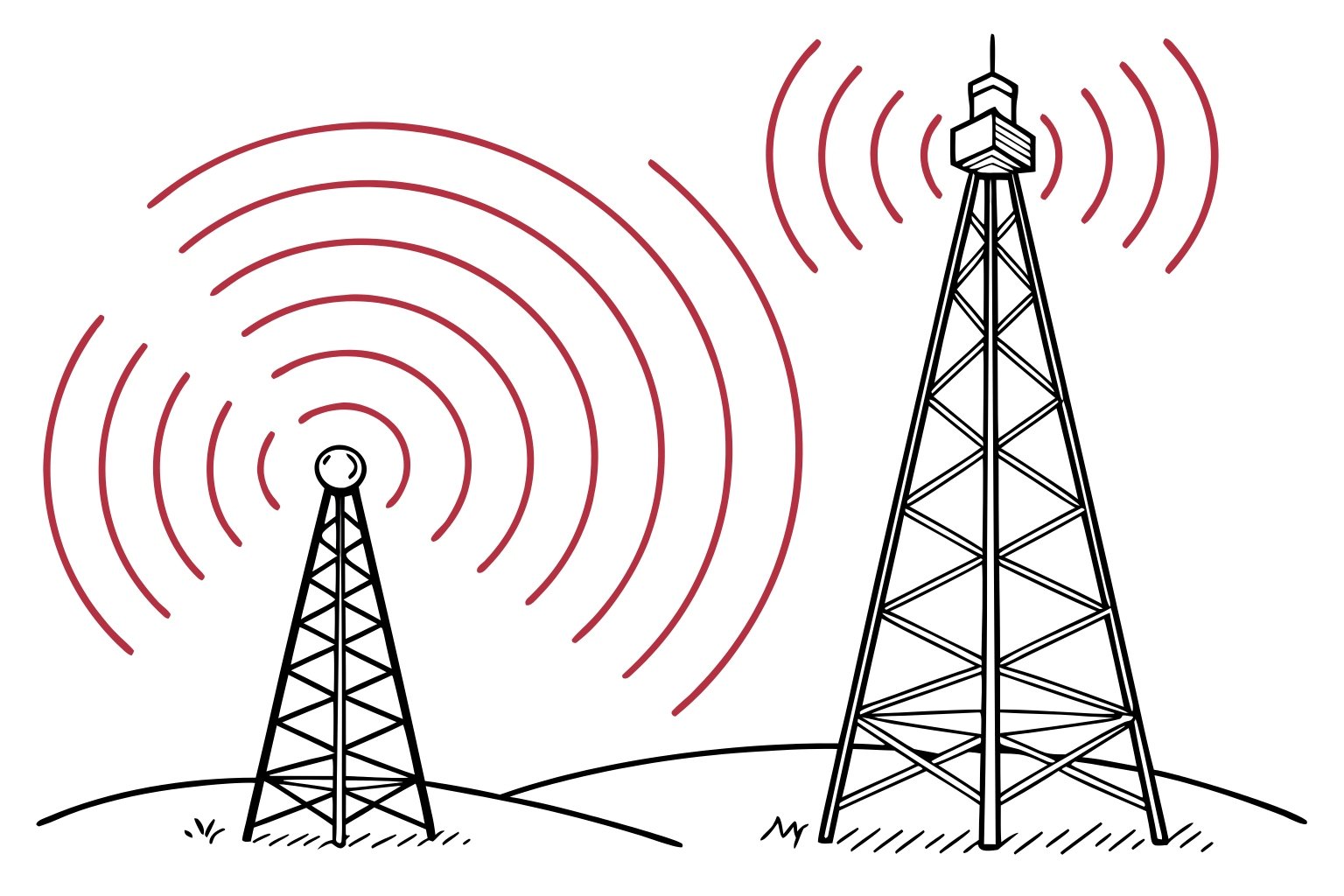
Phase 2: Antenna System Mistakes That Waste Your Transmitter Power
Your antenna system delivers the transmitter’s power to your coverage area. Mistakes here waste half your power or more.
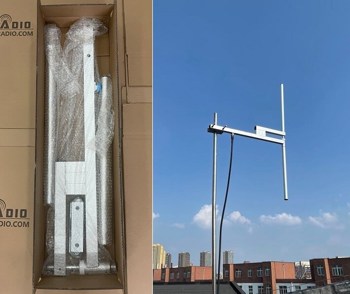
Mistake #3: Installing Antenna Too Low or With Obstructions
Why This Mistake Happens
You mount the antenna on an existing structure without considering height. Maybe the building owner restricts where you can place it. Or budget doesn’t allow a proper mast or tower. Or you underestimate how much height matters.
I see antennas mounted on single-story buildings surrounded by taller structures. Or placed behind rooftop equipment like HVAC units or water tanks. Or on short masts that barely clear nearby trees.
What Actually Goes Wrong
Low antenna placement limits coverage drastically. If surrounding buildings are taller than your antenna, they block your signal. Trees attenuate signals, especially when wet. Even partial blocking in one direction creates dead zones.
Height affects coverage more than most engineers realize. Doubling antenna height often improves coverage more than doubling transmitter power. I’ve seen stations dramatically improve coverage just by relocating the antenna higher without changing anything else.
Obstructions cause problems even when they seem small. A water tank 10 meters from your antenna blocks signal in that direction. HVAC equipment creates reflections and standing waves. Other antennas cause interference patterns.
The Right Way
Prioritize antenna height in your budget. If you must choose between a more powerful transmitter and better antenna placement, choose the antenna height. A 30W transmitter with antenna at 40m height usually beats 100W at 15m height.
Survey the proposed antenna location from your coverage area. Can you see where the antenna will be? If not, the signal will be blocked. Walk around the rooftop or tower base and verify the antenna will have clear line of sight in all directions.
Consider seasonal changes. Trees lose leaves in winter but block signals when leafed out. Plan for worst-case conditions year-round.
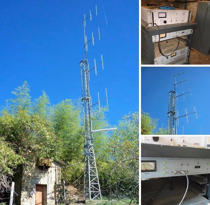
Options for achieving height include rooftop masts, building monopoles, guyed towers, or self-supporting towers. Sometimes renting space on an existing tower is more economical than building your own. Compare options based on your specific site and budget.
Height Guidelines
For community and campus radio, try to achieve 30m antenna height minimum. More is better. For drive-in cinema or very local coverage, 15-20m might work. For regional coverage, you need 40m or more.
The exact height needed depends on terrain and obstacles. Flat areas with few buildings need less height than hilly or urban areas.
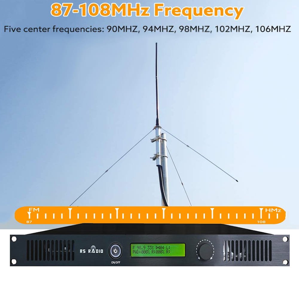
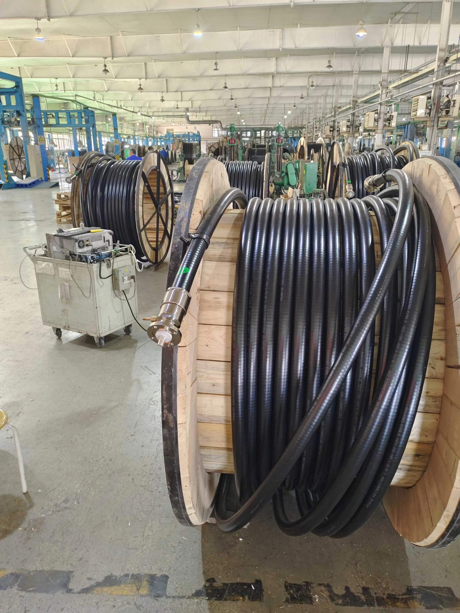
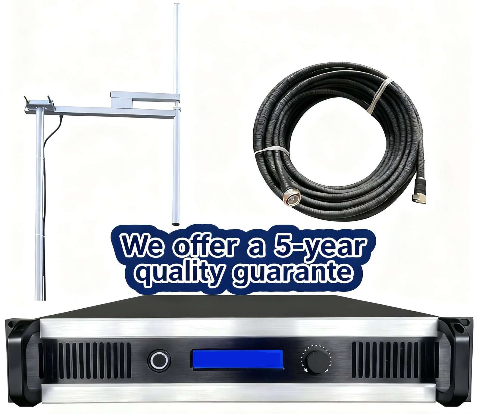
Mistake #4: Using Poor Quality Cable or Wrong Cable Type
Why This Mistake Happens
You view coaxial cable as a commodity—any 50Ω cable should work. Budget pressure tempts you toward cheaper options. Or you use cable designed for receive applications like satellite TV on transmit. Or you underestimate how much loss occurs in long cable runs.
I’ve seen installations with miniature coax on 100W transmitters, or cable TV coax used for broadcast, or cable purchased from consumer electronics stores rather than professional RF suppliers.
What Actually Goes Wrong
Cable loss wastes your transmitter power. Poor quality cable has high loss per meter. Over a 30-40m run, this loss becomes significant. Your 100W transmitter might only deliver 50-60W to the antenna.
The loss also generates heat in the cable. This accelerates cable degradation, especially in outdoor installations. After a year or two, the loss increases further as the cable deteriorates.
Weather resistance matters for outdoor installations. Consumer-grade cable isn’t designed for UV exposure, temperature extremes, or moisture. The jacket cracks, water enters, and performance degrades rapidly.
The Right Way
Match cable quality to your transmitter power and cable length. For runs under 10m with power under 50W, standard RG-8X works. For longer runs or higher power, use LMR-400 or equivalent low-loss cable. For professional permanent installations, consider hardline—it costs more initially but lasts decades.
Calculate the actual loss for your specific cable length and frequency. Cable manufacturers publish loss figures per meter. Add up the total loss and verify it’s acceptable. Try to keep total cable loss under 2 dB if possible.
Invest in quality connectors. Cheap connectors have poor weather sealing and corrode quickly. Use professional broadcast-grade connectors and install them carefully according to manufacturer instructions.
Weather seal all outdoor connections properly. Use self-amalgamating tape wrapped around the connector, then cover with vinyl weatherproofing tape or heat shrink. This prevents moisture entry that causes corrosion and loss.
Support the cable properly along its route. Use cable hangers or clamps every meter or two. Don’t let cable hang by its connectors or create sharp bends that stress the jacket.
Cable Selection by Application
For temporary or portable setups, RG-8X or LMR-240 provides reasonable performance with flexibility. For permanent outdoor installations, LMR-400 or equivalent is the minimum standard. For high power or very long runs, hardline becomes cost-effective despite higher initial expense.
Professional installers often use slightly better cable than minimum requirements because the performance margin protects against future degradation.
Mistake #5: Not Measuring and Monitoring VSWR
Why This Mistake Happens
You connect transmitter to antenna, see power output on the meter, and assume everything is correct. Maybe you check SWR once during installation but never again. Or you don’t own an SWR meter and rely on the transmitter’s built-in meter, which might be inaccurate.
Many installers view SWR as something to check only if problems appear rather than something to monitor regularly.
What Actually Goes Wrong
High SWR reflects power back to the transmitter instead of radiating it. This reflected power becomes heat that stresses the transmitter’s output stage. Over time, this stress causes premature component failure.
SWR changes over time as antenna systems age. Weather causes connector corrosion. Water enters coax through small jacket cracks. Antenna elements corrode or bend. These changes increase SWR gradually.
Without regular monitoring, you don’t notice the gradual SWR increase. The transmitter runs hot, output power slowly declines, and eventually something fails. What could have been prevented with a simple connector replacement becomes an expensive amplifier repair.
The Right Way
Measure SWR accurately during installation using a quality external meter or antenna analyzer. Don’t rely solely on the transmitter’s built-in meter because these are often approximate rather than precise.
Document your baseline SWR reading. Write it on a label near the transmitter or in your installation documentation. This becomes your reference for future monitoring.
Check SWR monthly during the first year. After that, quarterly checks work if readings remain stable. Always check after severe weather events like lightning storms, heavy wind, or ice.
Investigate any SWR increase. Even a change from 1.2:1 to 1.4:1 indicates something changed in your antenna system. Find and fix the problem before it gets worse.
Understand what good and bad SWR means. Under 1.3:1 is excellent. Between 1.3:1 and 1.5:1 is acceptable. Between 1.5:1 and 2.0:1 suggests investigation. Above 2.0:1 will damage your transmitter over time and should be corrected immediately.
Troubleshooting High SWR
If SWR increases, first check all connections. Loose connectors are the most common cause. Next, inspect the cable for visible damage. Finally, check the antenna elements for corrosion or physical damage.
Measure SWR at different points. If SWR is good at the antenna but bad at the transmitter, the problem is in the cable. If SWR is bad at both locations, the problem is the antenna.
Phase 3: Power and Ground Problems That Create Noise and Risk
Proper electrical installation ensures clean audio, stable operation, and protection from faults.
Mistake #6: Inadequate or Improper Grounding
Why This Mistake Happens
You connect the transmitter ground terminal to a nearby metal object like building steel or a water pipe. Or you use thin wire because it’s convenient. Or you don’t ground at all because the transmitter seems to work fine without it.
Grounding seems simple but actually requires specific techniques. Many engineers lack training in proper RF grounding methods.
What Actually Goes Wrong
Poor grounding creates multiple problems. Without proper earth connection, static builds up and damages equipment. Lightning energy has no path to ground and destroys electronics. Audio picks up hum and noise from ground potential differences.
Thin ground wires have high impedance at radio frequencies. They don’t provide effective RF ground even though they might work for AC safety. RF currents flow on the outside of conductors (skin effect), so wire size matters more than you might expect.
Building steel or water pipes seem like grounds but often aren’t connected to earth nearby. Long paths through building structure create high impedance. This defeats the purpose of grounding.
The Right Way
Install a proper ground rod system near the transmitter. Drive copper-clad steel ground rods at least 2.4m deep. In poor soil, multiple rods spaced several meters apart and bonded together work better than a single rod.
Use adequate conductor size for the ground connection. Minimum 10 AWG for low power transmitters, but 6 AWG or larger is better for permanent installations. Professionals often use copper strap rather than wire for lower impedance.
Keep ground conductor length short. Try to stay under 3m from transmitter to ground rod. Longer paths increase impedance and reduce effectiveness.
Create a single-point ground system. All equipment grounds connect to a common bus bar, which connects to the ground rod. This prevents ground loops where current flows through audio and signal cables.
Bond the coax shield to ground at the building entry point. Use a commercial coax grounding block designed for this purpose. This provides a path for lightning energy on the cable shield.
Grounding Indicators
Good grounding typically eliminates hum in audio. If you hear 50Hz or 60Hz hum, ground problems are likely. RF feedback (squeals or whistles near microphones) also suggests grounding issues. Static shocks from equipment housings definitely indicate missing or poor grounds.
Mistake #7: Not Protecting Against Power Quality Problems
Why This Mistake Happens
You plug the transmitter into a wall outlet assuming building power is adequate. Or you use a basic power strip without any conditioning. Or you don’t consider voltage fluctuations in areas with inconsistent power.
Most engineers assume professional equipment handles normal power variations. But transmitters are sensitive to power quality problems.
What Actually Goes Wrong
Voltage fluctuations stress power supply components. Sustained low voltage overworks the power supply trying to maintain output. High voltage stresses components and can cause immediate damage.
Electrical noise from other equipment couples into the transmitter through power lines. Motors, fluorescent lights, and HVAC systems inject noise that appears as hum or buzzes in your audio.
Power transients from switching or distant lightning can damage sensitive circuits. Even brief voltage spikes that don’t affect lights or motors can destroy transmitter components.
The Right Way
Test your power quality before installation. Use a multimeter to measure voltage over several hours or days. Note the highest and lowest readings. Acceptable variation is within 5% of nominal—for 230V power, that’s 220-240V range.
If voltage varies more than 10%, install a voltage regulator or line-interactive UPS. These devices maintain stable output voltage despite input fluctuations. Size the regulator for at least 150% of your transmitter’s AC power draw.
Use quality surge protection at minimum. Don’t use cheap power strips. Get a surge protector with adequate joule rating and indicator lights that show it’s functioning.
Consider a power line conditioner for sites with noisy power. These filter electrical noise and provide surge protection. The improvement in audio quality often justifies the cost.
Install the transmitter on a dedicated circuit breaker if possible. Don’t share the circuit with motors, compressors, or other heavy loads. This reduces voltage sag when other equipment starts.
Power Protection Levels
At minimum, use a quality surge protector. Better is a line conditioner with surge protection. Best is a voltage regulator or UPS for sites with poor power quality. Match your protection level to the reliability of your local power.
Phase 4: Environment and Interference Issues
Installation environment affects performance and reliability more than most engineers expect.
Mistake #8: Not Considering RF Environment and Interference
Why This Mistake Happens
You choose transmitter location based on convenience—available space, accessibility, or existing equipment rooms. You don’t survey the RF environment first. You assume the transmitter will work anywhere.
Modern buildings have dense RF from cellular systems, WiFi, two-way radios, and other transmitters. These sources can interfere with your transmitter or be affected by it.
What Actually Goes Wrong
Your transmitter’s RF energy can interfere with nearby electronics. I’ve heard reports of WiFi networks experiencing problems when transmitters operate, telephone systems picking up audio, or computers showing interference.
Other RF sources can affect your transmitter’s performance. Strong nearby signals can create intermodulation products or inject noise into your system. Close proximity to metal structures can distort your antenna pattern.
Poor RF shielding on the transmitter or connections allows RF energy to leak. This energy couples into nearby cables and equipment, causing interference.
The Right Way
Survey the installation site before placing equipment. Identify nearby transmitters, cellular towers, and two-way radio systems. Note sensitive equipment that might be affected by RF.
Maintain reasonable separation from sensitive electronics. Keep at least 3-5m distance from computers, medical equipment, and telephone systems if possible. More distance is always better.
Ensure good RF shielding on your transmitter and all connections. Don’t operate the transmitter with panels removed. Verify all RF connections are tight. Use shielded audio cables, not unshielded.
Consider a dedicated transmitter room if possible. This isolates RF equipment from offices and sensitive electronics. The room should have adequate ventilation for heat dissipation.
Test for interference before and after installation. Check that nearby equipment functions normally. Walk around with an AM radio near the transmitter—you should hear little or no RF noise. Strong noise suggests shielding problems.
Interference Prevention
Most interference problems stem from poor installation practice rather than equipment issues. Proper shielding, good connections, and adequate separation prevent the majority of problems. If interference occurs despite proper installation, ferrite chokes on affected cables often help.
Mistake #9: Poor Audio Cable Management and Shielding
Why This Mistake Happens
You run audio cables alongside power cables because it’s the convenient route. Or you use unshielded cables thinking audio doesn’t need shielding. Or you coil excess cable neatly without realizing this creates interference pickup.
I see beautiful transmitter installations ruined by buzzing audio from poor cable management. The technical setup is perfect but audio quality is poor.
What Actually Goes Wrong
Audio cables running parallel to AC power pick up magnetic hum. The 50Hz or 60Hz tone becomes audible in your broadcast. Longer parallel runs create worse pickup.
Unshielded audio cables act as antennas for RF and electrical noise. They pick up signals from nearby transmitters, cellular phones, and electrical equipment. This noise gets amplified and broadcast.
Coiled excess cable forms an inductor that magnifies magnetic pickup. The neat coil becomes an efficient noise collector.
Ground potential differences between equipment locations create hum through cable shields. This is called ground loop hum.
The Right Way
Use shielded balanced cables for all audio connections longer than 1-2m. XLR cables provide the best noise rejection. The shielding blocks RF and electric field coupling, while the balanced signal rejects magnetic hum.
Route audio cables away from AC power. Maintain at least 30cm separation. If cables must cross, make them cross at 90° to minimize coupling. Never run audio and power parallel for long distances.
Avoid coiling excess cable. If cable is too long, fold it back and forth in 20-30cm sections, or cut it to proper length. Don’t make neat circular coils.
Keep audio cable runs as short as practical. Longer cables pick up more interference. Plan equipment placement to minimize cable lengths.
Use quality connectors and verify shield continuity. The cable shield should connect properly at both ends. Poor connector assembly defeats the shielding.
Ground Loop Solutions
If hum persists despite shielded cables and proper routing, you might have a ground loop. Try lifting the shield connection at the receiving end only. This breaks the ground loop while maintaining RF shielding. If problems continue, use an audio transformer isolator.
Phase 5: Testing and Monitoring Failures
Final mistakes occur when commissioning is rushed or monitoring is neglected.
Mistake #10: Inadequate Testing and No Ongoing Monitoring
Why This Mistake Happens
You turn on the transmitter, hear audio on a receiver, see power output on the meter, and declare installation complete. Maybe you’re rushing to meet a deadline. Or you don’t have proper test equipment. Or you assume if it works, it’s correct.
Most installations I review have no documentation of initial performance. When problems develop, there’s no baseline to compare against.
What Actually Goes Wrong
Without proper testing, you don’t know if the system is performing correctly. Maybe the frequency is slightly wrong. Or modulation is too low so the broadcast sounds weak. Or audio processing is misconfigured. The transmitter works but not optimally.
Without ongoing monitoring, you don’t notice gradual degradation. Coverage slowly shrinks as antenna system deteriorates. Audio quality decreases as components age. Output power declines. By the time problems become obvious, multiple issues have developed.
I’ve supported customers who called about sudden coverage loss, only to find the problem had been developing for months. Without monitoring, they didn’t notice the gradual decline.
The Right Way
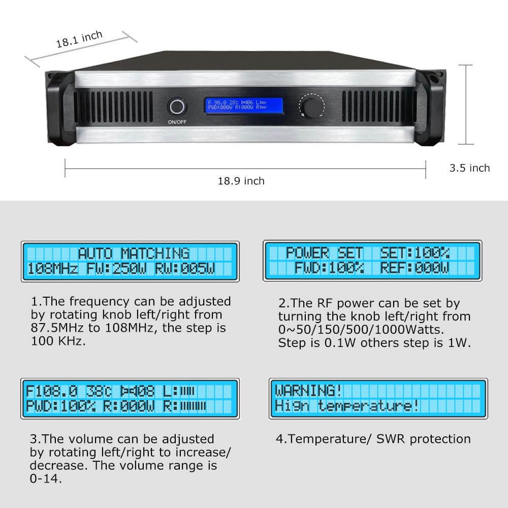
Verify frequency accuracy during commissioning. Use a frequency counter or quality receiver with digital frequency display. Confirm you’re operating on the correct assigned frequency.
Check modulation depth. Too much modulation distorts and creates splatter interference. Too little makes your signal weak compared to other stations. Proper modulation maximizes loudness without distortion.
Test audio frequency response. Your broadcast should sound like the studio feed. If bass or treble is emphasized or missing, audio processing needs adjustment.
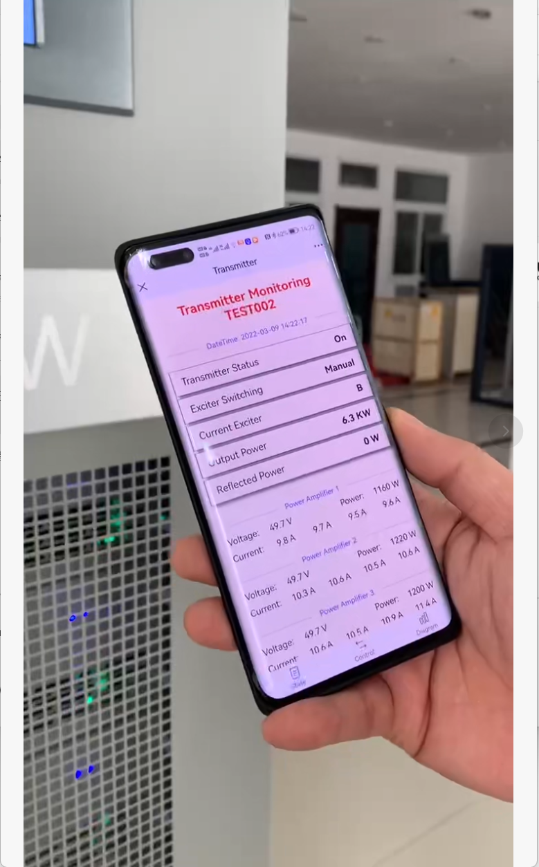
Measure power output and SWR accurately. Use a quality RF power meter, not just the transmitter’s built-in meter. Document these baseline readings.
Drive your coverage area with a receiver. Note signal strength at key locations. Identify any dead zones or weak areas. This becomes your coverage baseline.
Document everything. Write down all measurements, take photos of the installation, and file this information where future maintenance personnel can find it.
Ongoing Monitoring
Check the transmitter regularly after installation. Weekly quick checks verify operation. Monthly detailed checks include recording meter readings, checking audio quality, and visual inspection. Quarterly testing should include detailed measurements of frequency, modulation, and coverage.
Keep a log of all readings. Simple spreadsheet works fine. The log lets you spot trends—gradual power decline or SWR increase indicates developing problems you can fix before they become failures.
Set up a simple monitoring schedule and stick to it. Maybe 15 minutes per month prevents expensive repairs and maintains broadcast quality.
Testing Equipment
You don’t need expensive test gear for basic monitoring. A quality FM receiver, an RF power meter, and a basic multimeter handle most needs. For commissioning, consider hiring a test service if you lack specialized equipment like modulation monitors or spectrum analyzers.
Why These Mistakes Keep Happening
I see these same 10 mistakes across hundreds of installations worldwide. The pattern is consistent—engineers focus on the transmitter itself while neglecting the system around it. Site selection, antenna placement, cabling, power quality, and testing get treated as minor details instead of critical factors.
Budget pressure tempts shortcuts. Proper cable costs more than cheap cable. Quality power conditioning costs more than a basic power strip. Professional testing costs money. These seem optional until problems develop.
Time pressure rushes installation. Taking extra time to route cables properly or establish monitoring systems feels wasteful when the transmitter is already working. Until it stops working later.
Knowledge gaps exist. Not every engineer has RF and broadcast experience. Some of these issues require specialized knowledge that general technicians may lack.
The Real Cost
Cutting corners during installation creates problems that cost more to fix than doing it correctly initially. I’ve seen this pattern many times—save a bit during installation, spend much more on repairs and downtime.
Beyond direct costs, poor installation damages your reputation. Listeners tune away from stations with weak coverage or poor audio quality. Community stations lose credibility when forced offline by preventable equipment failures.
The Smart Approach
Budget properly from the start. Installation costs more than just the transmitter price. Plan for quality cables, proper power systems, antenna mounting, and testing.
Allow adequate time. Professional installation takes days, not hours. Rushing creates mistakes.
Learn proper techniques or consult with experienced broadcast engineers. Every manufacturer provides technical support—use it. At RS, we offer installation guidance to help customers avoid these mistakes.
Test thoroughly during commissioning. Document baseline performance. Monitor regularly after installation. These practices catch small problems before they become big failures.
Getting Installation Right
At RS, we support FM transmitter installations worldwide. Before shipping equipment, our engineers discuss the installation plan with customers. We review coverage requirements, antenna placement, power quality, and testing capabilities. This consultation prevents planning mistakes.
During installation, we’re available via WhatsApp for real-time support. Customers send photos and meter readings. We verify everything looks correct before powering up. This remote guidance has prevented many installation errors.
We provide complete system solutions including transmitter, antenna, and coaxial cable matched to your application. Our 5-year warranty covers equipment, but proper installation is necessary to avoid problems.
If you’re planning an FM transmitter installation, contact RS technical support for consultation. We help you avoid these common mistakes so your installation succeeds. The goal isn’t just getting on air—it’s staying on air reliably for years.
Visit https://fmradiotx.com/ for installation resources, transmitter selection guides, and technical support.