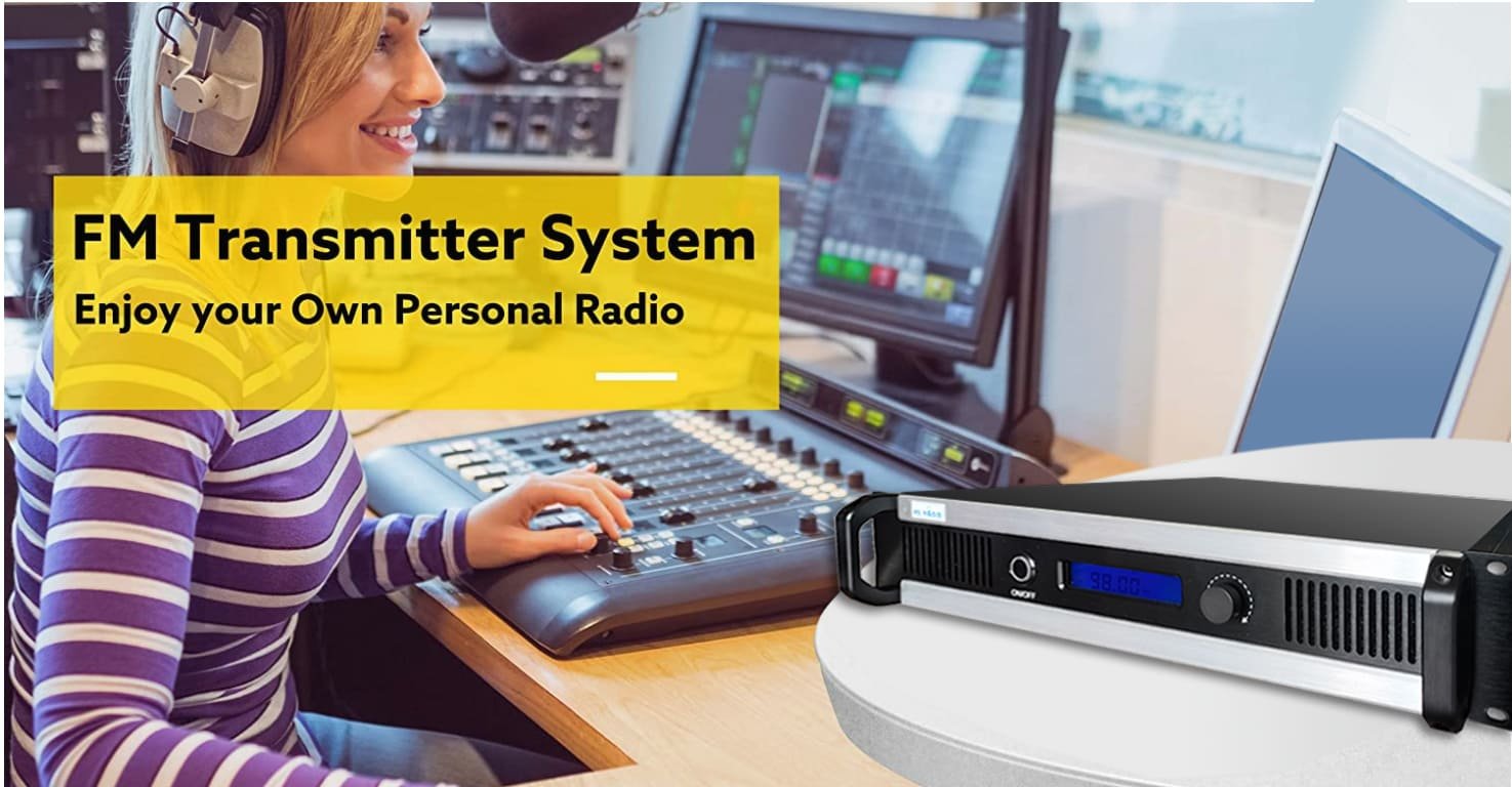
Top 10 FM Transmitter Buying Facts Every Broadcaster Should Know
I’m a technical engineer at RS supporting broadcast stations worldwide. Over the past years, I’ve helped hundreds of stations select and install FM transmitters. Maybe you’re planning your first broadcast project or upgrading existing equipment. Either way, the decisions you make now affect your operations for the next 10-15 years.
I notice most buyers focus heavily on transmitter power and price. Those matter, but they’re just starting points. Real-world broadcasting success depends on factors many overlook until problems appear. This guide shares what I’ve learned helping stations avoid expensive mistakes and build reliable broadcast systems.
1. Coverage Planning: Power + Antenna + Terrain = Real Coverage
Why Simple Power Ratings Mislead
"I need 500W for 20km coverage" – I hear this weekly. The reality is more complex. Transmitter power alone doesn’t determine coverage. Three factors work together: transmitter output, antenna system, and terrain environment.
Let me explain with real numbers. A 300W transmitter connected to a basic dipole antenna at 30m height covers differently than the same transmitter with a 4-bay high-gain antenna at 60m. The second setup might deliver 50% more coverage without changing transmitter power.
Understanding ERP (Effective Radiated Power)
Here’s what actually determines coverage:
- Transmitter Output Power: What the transmitter produces
- Feedline Loss: Cable between transmitter and antenna (typically 1-3 dB)
- Antenna Gain: How antenna focuses energy (0 to 6+ dB)
- ERP = Transmitter Power – Feedline Loss + Antenna Gain
Real Coverage Factors
| Factor | Impact on Coverage | What You Control |
|---|---|---|
| Antenna Height | 40-50% increase doubling height | Site selection, tower investment |
| Terrain Type | Flat: maximum coverage Hilly: 30-50% reduction Mountains: 50-70% reduction |
Site selection, possibly multiple transmitters |
| Frequency | Lower FM (88-92 MHz) propagates 10-15% better than upper (106-108) | Frequency application (limited control) |
| Antenna Pattern | Omnidirectional vs directional shapes coverage | Antenna selection |
| Regulatory Limits | Many countries cap ERP regardless of transmitter power | Licensing research |
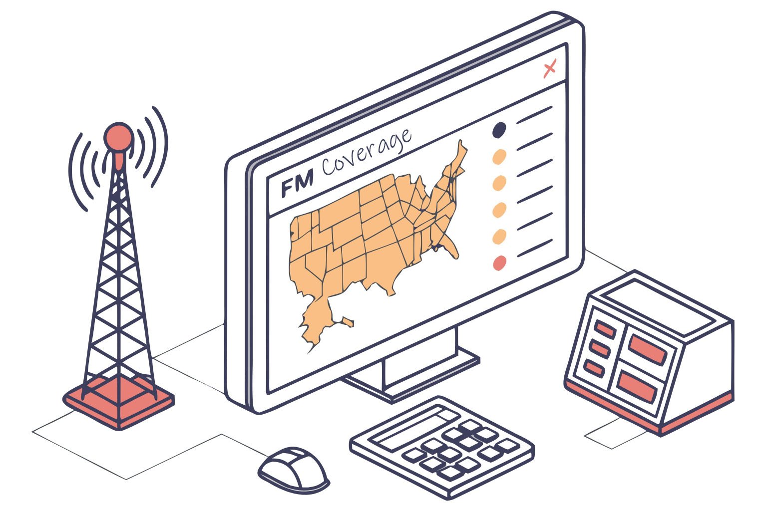
How I Help Stations Plan Coverage
When you’re evaluating transmitters, I recommend professional coverage analysis. I use propagation modeling software analyzing your actual location, terrain data, and antenna specifications. The output shows realistic coverage contours, not optimistic marketing numbers.
Recently I worked with a county broadcaster needing 25km coverage in hilly terrain. They initially specified a 1000W transmitter ($1,890). After terrain analysis, I recommended 500W ($1,560) with a taller tower and better antenna. Total system cost was $2,000 less and delivered superior coverage. The key was proper system design, not just bigger transmitter.
Coverage Estimates with 30m Antenna (Flat Terrain)
| Transmitter Power | Typical Coverage Radius | Best Applications |
|---|---|---|
| 15W | 1-3 km | Campus radio, neighborhood ministry |
| 50W | 3-5 km | Town community stations |
| 100W | 7-12 km | Small city coverage |
| 300W | 15-20 km | County-level broadcasting |
| 500W | 20-25 km | Regional coverage |
| 1000W | 25-30 km | Metropolitan area |
Note: These are general estimates. Actual coverage varies significantly with terrain, antenna height, and local conditions. I provide site-specific predictions for serious projects.
My Recommendation
Don’t specify transmitter power without coverage analysis. Contact me with your location and coverage goals. I’ll provide free professional coverage modeling showing what’s actually achievable. This prevents overbuying (wasting money) or underbuying (insufficient coverage).
2. System Integration: How Transmitters Connect to Your Broadcast Chain
Beyond Basic Audio Connections
Modern broadcast systems integrate multiple devices: audio processors, stereo encoders, RDS systems, automation software, and studio-transmitter links. The transmitter must work seamlessly with all of them.
I help stations evaluate compatibility before purchase. Integration problems discovered after delivery cause expensive delays and frustration.
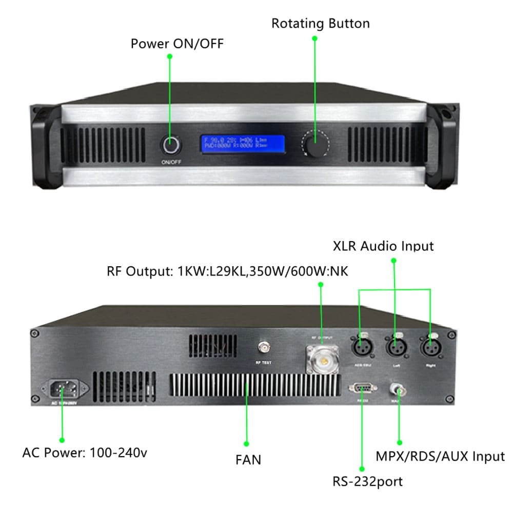
Essential Audio Input Options
| Input Type | Purpose | When You Need It |
|---|---|---|
| Balanced XLR | Industry standard analog audio | Most installations, direct from mixer |
| AES/EBU Digital | Digital audio (eliminates analog conversion) | High-quality chains, digital studios |
| MPX Composite | Accepts pre-processed stereo+RDS signal | Using external audio processor (Orban, Omnia, etc.) |
| IP Audio Streaming | Network audio delivery | Modern IP-based STL links |
RS transmitters include all these inputs on 100W+ models. Lower power units (15-50W) include XLR and sometimes AES/EBU depending on model. This flexibility accommodates different studio configurations.
Stereo Encoder Performance
FM stereo encoding quality directly affects your broadcast sound. Key specifications I verify:
- Stereo Separation: Minimum 50 dB professional grade; 60+ dB excellent. RS transmitters achieve 65 dB.
- Frequency Response: ±0.5 dB from 50Hz-15kHz maintains audio balance
- Pilot Tone Accuracy: ±2 Hz prevents receiver decoding problems
- THD: <0.1% preserves audio quality
RDS/RBDS Integration
Radio Data System adds station identification, program information, and other text data to your FM signal. Professional broadcasters consider this essential. Internal RDS encoders simplify installation and reduce costs versus external units.
RS transmitters include RDS encoders supporting standard features:
- Station name (PS)
- Scrolling text (RadioText)
- Program type identification
- Traffic announcements
- Time/date
Audio Processing Integration
Many professional stations use dedicated audio processors optimizing loudness and sound signature. These devices output composite MPX signals bypassing the transmitter’s internal audio processing.
If you plan using external processors, verify transmitter supports composite MPX input at standard impedance (75Ω) and level (±75 kHz deviation). RS transmitters include this input on all models.
My Integration Experience
Recently I helped a station integrate RS transmitter with older Orban processor. The connection required understanding impedance matching and level calibration. I provided remote guidance via WhatsApp video call, and we completed integration in 30 minutes. Most integration questions resolve quickly with proper manufacturer support.
Recommendation
Before purchasing transmitters, document your existing equipment: audio processors, stereo encoders, automation systems, and STL equipment. Share this with transmitter manufacturers confirming compatibility. I review these configurations regularly, identifying potential issues before they become problems.
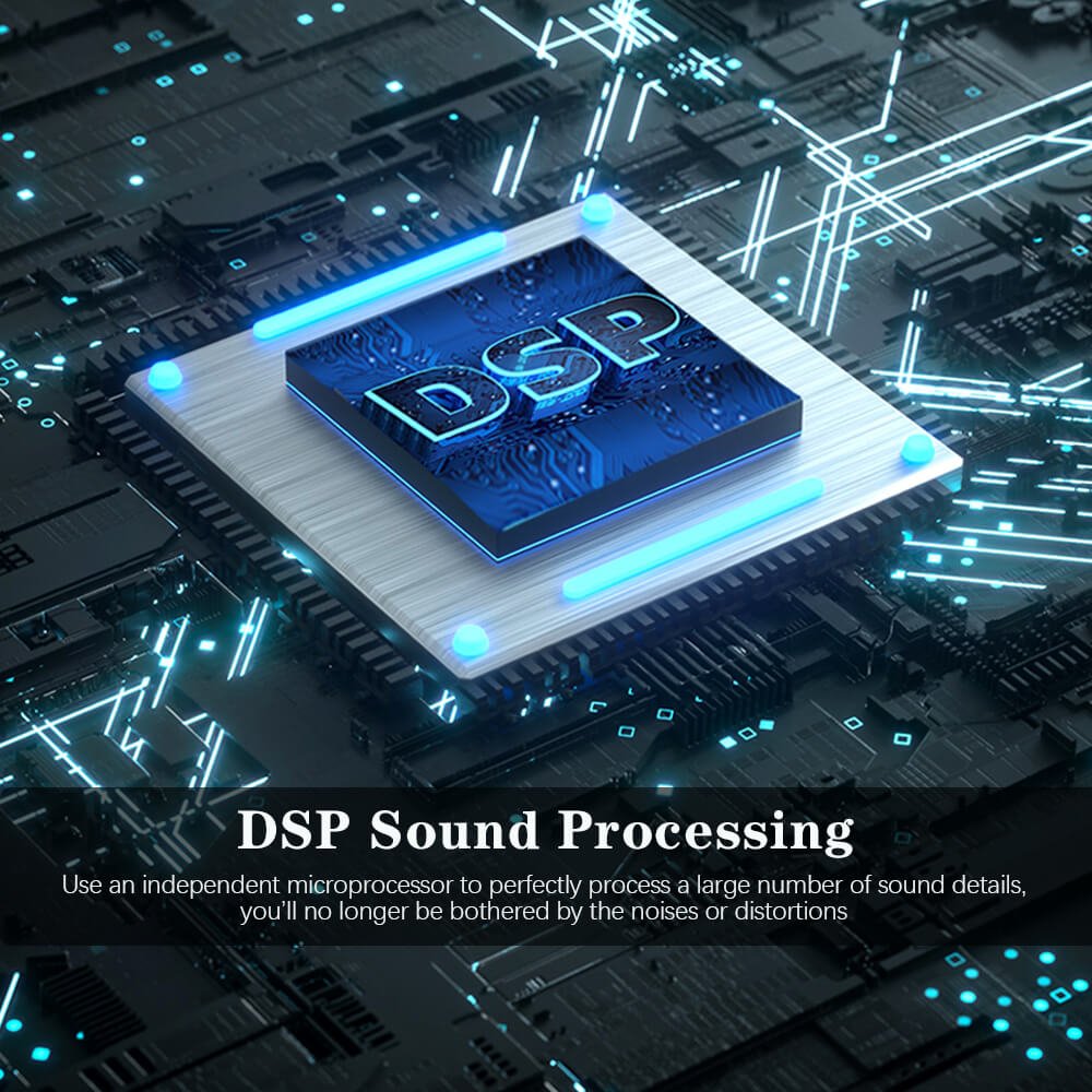
3. Audio Quality Specifications That Actually Matter
Technical Performance Defining Broadcast Sound
Audio quality specifications separate professional broadcast equipment from consumer-grade products. I measure transmitter performance helping stations understand which specifications truly affect broadcast quality.
Critical Specifications Explained
Total Harmonic Distortion (THD): Measures signal purity. Lower numbers mean cleaner audio. Professional standards require <0.5%. High-quality transmitters achieve <0.1%. RS transmitters specify <0.01% – essentially unmeasurable distortion contributing nothing to audio coloration.
I’ve tested dozens of transmitters. THD below 0.1% is effectively transparent. Above 0.3%, listeners might detect harshness during critical listening. Above 0.5%, distortion becomes audible on music broadcasts.
Signal-to-Noise Ratio (SNR): Determines background noise level affecting audio quietness. Minimum professional standard is 70 dB. Quality transmitters achieve 75-80 dB. RS transmitters deliver >80 dB SNR enabling full dynamic range without audible background hiss.
SNR matters particularly during quiet programming – speech, classical music, or pauses between songs. Lower SNR creates noticeable background hiss.
Audio Performance Comparison
| Specification | Minimum Professional | High Quality | RS Transmitters | Why It Matters |
|---|---|---|---|---|
| THD | <0.5% | <0.1% | <0.01% | Audio purity, musicality |
| SNR | >70 dB | >75 dB | >80 dB | Noise floor, dynamic range |
| Frequency Response | ±1.0 dB | ±0.5 dB | ±0.3 dB | Tonal balance |
| Stereo Separation | >50 dB | >60 dB | 65 dB | Stereo imaging |
RF Performance Specifications
Audio quality isn’t everything. RF output quality affects regulatory compliance and interference prevention:
Harmonic Suppression: Unwanted harmonics interfere with other services. Regulations require second harmonic suppression <-60 dBc. RS transmitters achieve <-75 dBc – significant margin above requirements.
I’ve investigated interference complaints. Transmitters barely meeting specifications when new often drift out of compliance as components age. Margin matters.
Spurious Emissions: Non-harmonic unwanted signals must stay below -70 dBc. Quality transmitters achieve -80 dBc across the entire spectrum.
Adjacent Channel Power: Clean modulation prevents energy spillover interfering with neighboring stations. Professional transmitters maintain 10+ dB margin meeting ITU-R mask requirements.
Carrier Frequency Accuracy: Regulations typically allow ±2000 Hz deviation. Professional transmitters maintain ±200 Hz. RS transmitters achieve ±100 Hz using high-stability PLL synthesis – twenty times better than regulatory minimums.
How Specifications Affect Real Operations
Better specifications translate directly into:
- Cleaner sound quality listeners appreciate
- Fewer interference complaints from adjacent stations
- Easy regulatory compliance during inspections
- Professional credibility competing with major broadcasters
RF Performance Standards
| Parameter | Regulatory Requirement | RS Performance | Margin |
|---|---|---|---|
| 2nd Harmonic | <-60 dBc | <-75 dBc | 15 dB margin |
| Spurious Emissions | <-70 dBc | <-80 dBc | 10 dB margin |
| Frequency Stability | ±2000 Hz | ±100 Hz | 20x better |
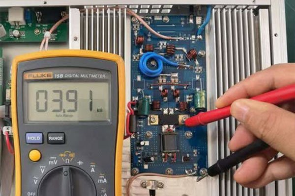
My Testing Experience
I individually test transmitters before shipment. Every unit comes with measured data documenting actual performance – not just specification sheet claims. This quality control catches occasional outliers and gives customers confidence in equipment performance.
Recommendation
Demand complete technical specifications including measurement conditions. Compare against international broadcast standards (ITU-R recommendations) and local regulations. Request actual test data, not just specification claims. Quality manufacturers provide measured results for every unit.
4. Reliability Features: Minimizing Broadcast Interruptions
The Real Cost of Downtime
Broadcast interruptions cost audience, revenue, and credibility. I design high-reliability systems understanding professional transmitters must deliver 99.9%+ uptime – less than 9 hours downtime yearly.
Why Reliability Matters by Station Type
- Commercial Stations: Advertising revenue depends on continuous operation. Every hour offline loses money directly.
- Public Service Broadcasters: Emergency information requires reliable transmission. Some face regulatory uptime requirements.
- Religious Broadcasters: Listener engagement and donation revenue depend on consistent service.
- Community Stations: Limited budgets make downtime particularly damaging. Can’t afford emergency service calls.
Built-in Protection Systems
Quality transmitters include multiple protection systems preventing catastrophic failures:
Over-Temperature Protection: Automatic power reduction when temperatures exceed safe thresholds. RS transmitters activate protection at 60°C – well below component damage levels. System continues reduced-power operation rather than complete shutdown.
I’ve seen this work. A station’s cooling fan failed during hot weather. The transmitter automatically reduced power by 30% and alerted operators. Broadcast continued while scheduling fan replacement. Without protection, the transmitter would have failed completely.
High SWR Protection: Antenna system problems create reflected power damaging transmitters. Automatic power reduction protects amplifiers while allowing continued low-power operation.
Cooling System Redundancy: RS transmitters 500W+ include multiple fans with individual monitoring. Single fan failure doesn’t cause shutdown – remaining fans handle thermal load while alerting operators.
Redundancy Strategies
| Configuration | Description | Downtime | Cost | Best For |
|---|---|---|---|---|
| Single Transmitter | One transmitter with good protection systems | Hours (part replacement) | Lowest | Small stations accepting some downtime |
| Cold Standby | Backup transmitter available, manual switch | Minutes to hours | Low | Stations with technical staff available |
| Warm Standby | Backup transmitter ready, auto switch | 2-10 seconds | Medium | Most professional applications |
| Hot Standby (1+1) | Both transmitters operating, instant failover | Zero | Highest | Major market commercial, critical service |
| N+1 Modular | Multiple PA modules, operation continues with one failed | None (reduced power) | Medium-High | 1000W+ installations |
Calculating Reliability ROI
Example: 500W commercial station generating $10,000 monthly revenue.
- Hot standby costs $3,000 additional (backup transmitter + switching)
- Single 24-hour failure loses approximately $330 revenue plus listener disruption
- Payback after 9 failures
- Statistics suggest 2-3 major failures over 10 years
- System pays for itself while protecting revenue and reputation
Monitoring and Alarming
Reliability requires knowing transmitter status immediately:
- Real-Time Monitoring: Continuous measurement of power, frequency, SWR, temperature, voltages
- Alarm Notifications: Email and SMS alerts when problems occur
- Event Logging: Detailed records for troubleshooting and regulatory documentation
- Remote Monitoring: Network connectivity enables off-site oversight
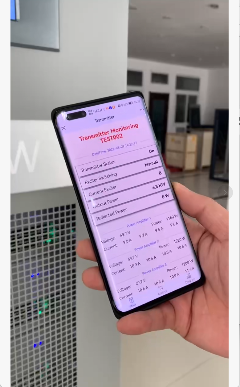
RS transmitters 100W+ include Ethernet monitoring standard. I can check transmitter status from anywhere via web browser or smartphone.
RS Reliability Track Record
- Mean Time Between Failures (MTBF): >50,000 hours in professional applications
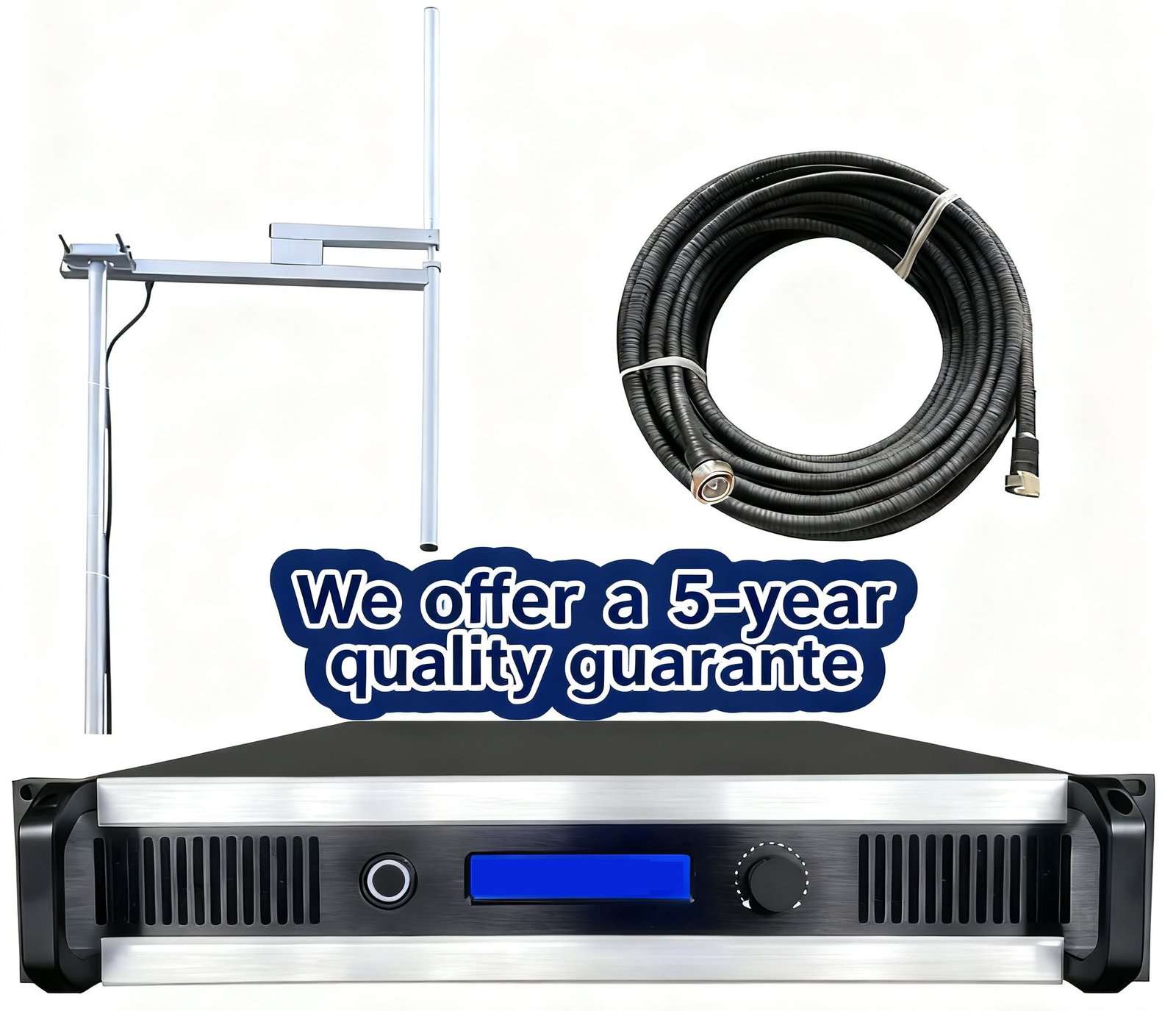
- 5-year comprehensive warranty (industry-leading)
- 24/7 engineering support via WhatsApp
- Global spare parts delivery typically 3-5 days
Recommendation
Evaluate reliability requirements based on your station type and financial model. Calculate downtime costs including lost revenue, emergency service calls, and reputation damage. For commercial stations, redundancy usually justifies cost. Request MTBF data and warranty terms from manufacturers. Quality manufacturers provide detailed reliability information.
5. Energy Efficiency: The Hidden Long-Term Cost
Understanding Total Cost of Ownership
Purchase price represents only 20-40% of total transmitter ownership cost over 10 years. Energy consumption dominates long-term expenses. I help stations analyze total cost of ownership (TCO) revealing efficient transmitters often deliver lower TCO despite higher purchase prices.
Power Amplifier Efficiency Explained
Efficiency = RF Output Power ÷ DC Input Power
Example: 50% efficiency means 100W DC input produces 50W RF output. The other 50W becomes waste heat requiring cooling.
Modern LDMOS power amplifiers achieve 60-65% efficiency. RS transmitters use quality LDMOS amplifiers from established manufacturers (Ampleon, NXP) delivering 60-65% typical efficiency.
Real Energy Cost Calculation
Let me show you actual numbers for a 500W transmitter:
50% Efficient Transmitter:
- DC power required: 1,000W
- Annual energy (24/7): 8,760 kWh
- Annual cost at $0.15/kWh: $1,314
- 10-year energy cost: $13,140
65% Efficient Transmitter (RS Standard):
- DC power required: 770W
- Annual energy: 6,745 kWh
- Annual cost at $0.15/kWh: $1,012
- 10-year energy cost: $10,120
- Savings: $3,020 over 10 years
Energy Cost Comparison Table
| Transmitter Power | 50% Efficiency 10-Year Cost | 65% Efficiency 10-Year Cost | Savings |
|---|---|---|---|
| 100W | $2,628 | $2,024 | $604 |
| 300W | $7,884 | $6,072 | $1,812 |
| 500W | $13,140 | $10,120 | $3,020 |
| 1000W | $26,280 | $20,240 | $6,040 |
Calculated at $0.15/kWh electricity cost with 24/7 operation
Part-Load Efficiency Matters
Many stations operate at reduced power during nighttime. Amplifier efficiency at partial power significantly affects costs.
Some transmitters suffer dramatic efficiency drops at reduced power – 65% at full power declining to 40% at 50% power. RS transmitters maintain >55% efficiency from 20% to 100% power through advanced bias control.
Geographic Variations
Energy costs vary dramatically by location:
- Low-cost regions: $0.08-0.12/kWh
- Medium-cost regions: $0.15-0.25/kWh
- High-cost regions: $0.30-0.50/kWh
Higher energy costs accelerate payback for efficient transmitters. Stations in high-cost regions should prioritize efficiency heavily.
Cooling Cost Impact
Lower efficiency generates more waste heat requiring additional cooling. Air conditioning adds 20-40% to transmitter energy costs in climate-controlled facilities. Higher efficiency transmitters reduce both direct transmitter and indirect cooling energy consumption.
Total Cost of Ownership Example
Budget 500W Transmitter:
- Purchase: $1,200
- 10-year energy: $13,140
- Total: $14,340
RS Professional 500W Transmitter:
- Purchase: $1,560
- 10-year energy: $10,120
- Total: $11,680
- Net savings: $2,660
This excludes reliability and maintenance costs where professional transmitters deliver additional savings.
My Recommendation
Request complete efficiency specifications including full-power efficiency, part-load efficiency curves, and DC power consumption. Calculate TCO including 10-year energy costs at your local electricity rates. Include cooling costs if transmitter is in climate-controlled space. Compare TCO, not just purchase prices. Investment in efficient transmitters typically pays back within 2-4 years.
6. Modular Design: Fast Repairs Minimize Downtime
Why Maintainability Matters
Transmitter failures eventually occur. Design determines how quickly you restore service. I evaluate transmitter maintainability helping stations select equipment minimizing operational disruption and maintenance costs.

The Cost of Extended Downtime
- Emergency service calls: $200-500+ per hour
- Rush parts shipping: 50-200% surcharges
- Lost revenue during outages
- Listener loss from extended silence
- Technical staff overtime
- Reputation damage
Smart maintenance design minimizes these costs through fast diagnosis, quick repairs, and field-replaceable modules.
Modular Architecture Benefits
Hot-Swappable Modules: Critical components designed as plug-in modules replaceable without powering down. Power amplifier modules, power supplies, exciter modules, and cooling fans install/remove quickly. Failed modules ship for repair while transmitter continues with replacement modules.
I’ve guided many field repairs remotely. "Remove the three screws on PA module 2, unplug the connector, slide out the module." Five minutes later, spare module installed, transmitter back on air. This only works with proper modular design.
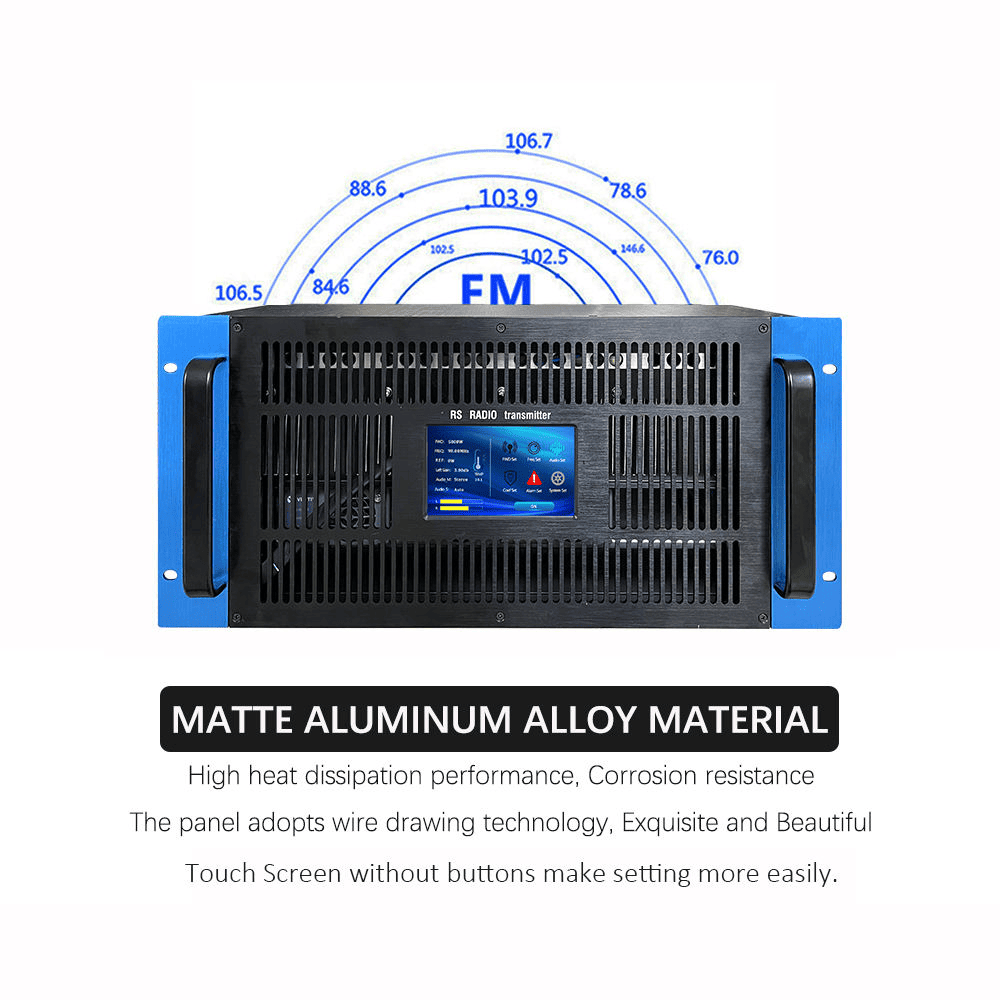
Front-Panel Accessibility: All serviceable components accessible from front panel. No need removing transmitter from rack or accessing rear connections during maintenance. Valuable in crowded equipment rooms.
Standardized Modules: RS uses common modules across product lines. One power supply design serves multiple transmitter models. Stations with multiple transmitters minimize spare parts inventory investment.
Diagnostic Features
Component-Level Fault Isolation: Advanced transmitters identify specific failed components. Not just "transmitter failed" but "PA module 3 over-temperature" or "exciter PLL unlock." This speeds diagnosis dramatically.
LED Status Indicators: Visual indicators on modules show operational status. Engineers quickly identify problems without complex test equipment. Green = normal; Red = fault. RS transmitters include comprehensive LED indicators on all modules.
Remote Diagnostic Capability: Network-connected transmitters enable remote diagnosis. I access detailed fault information from my office before dispatching to transmitter sites. Many problems diagnosed remotely saving service calls. Some fixed remotely through software updates or configuration changes.
Maintenance Service Comparison
| Feature | Basic Transmitter | Professional Transmitter (RS) |
|---|---|---|
| Module Design | Integrated, requires disassembly | Hot-swappable modules |
| Diagnostics | Basic fault indication | Component-level fault isolation |
| Front Access | Limited | Complete front-panel access |
| Documentation | Basic manual | Complete schematics + troubleshooting |
| Support | Business hours email | 24/7 WhatsApp engineering support |
| Spare Parts | Limited availability | Global 3-5 day delivery |
Spare Parts Strategy
For professional stations, I recommend stocking:
- One complete power amplifier module
- One power supply module (if modular)
- Set of cooling fans
- Exciter board or complete exciter
- Miscellaneous components (fuses, connectors)
This investment dramatically reduces downtime. Failed modules ship for repair while spare modules restore immediate operation.
RS Serviceability Advantages
- Fully modular design with hot-swappable PA and power supply modules
- Complete front-panel access
- Component-level fault diagnostics with specific error codes
- Comprehensive LED status indicators
- Complete service documentation including schematics
- 24/7 WhatsApp engineering support with remote diagnostics
- Global spare parts availability 3-5 day delivery
- 15-year parts availability commitment
- Modules compatible across transmitter product line
Real Service Example
Recently a station in Kenya experienced transmitter fault during peak broadcasting. The operator contacted me via WhatsApp. I remotely accessed the transmitter, reviewed fault logs, identified failed PA module. Spare module in stock locally, engineer replaced it in 10 minutes following my video call guidance. Total downtime: 25 minutes. With traditional designs, this could have been days waiting for factory service.
My Recommendation
Evaluate transmitter maintainability carefully. Request information on module design, diagnostic capabilities, spare parts availability, and technical support. Calculate potential downtime costs for your station. For professional broadcasting, modular design and comprehensive support justify higher initial investment through dramatically reduced lifetime maintenance costs.
7. Remote Monitoring: Essential for Unattended Sites
Modern Requirement, Not Optional Feature
I design broadcast facilities where transmitters often operate unattended at remote mountain or rural sites. Remote monitoring transformed from luxury to absolute requirement. Professional transmitters must integrate seamlessly with network management systems.
Critical Remote Functions
Real-Time Parameter Monitoring: Continuous access to all critical transmitter parameters from remote locations. View forward power, reflected power, modulation level, temperature, voltages, and frequency without site visits.
RS transmitters provide real-time monitoring of 50+ parameters through web interface accessible from any device with web browser. No special software required.
Historical Data Logging: Trend analysis identifies developing problems before failures occur. Temperature gradually increasing over weeks indicates cooling degradation. Reflected power slowly rising suggests antenna deterioration.
RS transmitters log parameters at 5-minute intervals with 12-month data retention. I can review trends identifying patterns invisible in real-time monitoring.
Alarm and Notification System: Immediate notification when problems occur minimizes downtime. Multiple notification methods ensure engineers receive alerts:
- Email alerts
- SMS text messages
- SNMP traps to network management systems
- Audio alarms at transmitter site
Configurable alarm thresholds customize for each station’s requirements. RS transmitters support comprehensive alarming with priority levels (critical/warning/information) and acknowledgment systems.
Remote Control Capabilities: Beyond monitoring, remote control enables corrective actions without site visits:
- Power on/off
- Power level adjustment
- Frequency selection
- Audio source switching
- Exciter failover activation
RS transmitters provide complete remote control via web interface, serial commands, or SNMP.
Network Management Features
| Feature | RS Implementation | Benefits |
|---|---|---|
| Web Interface | Embedded HTML5 server | Access from any device, no special software |
| SNMP Support | v2/v3 with complete MIB | Enterprise network management integration |
| RESTful API | JSON-based programmatic access | Custom automation integration |
| Mobile Access | Responsive design | Smartphone/tablet monitoring |
| Security | HTTPS, role-based authentication | Protected remote access |
| Data Logging | 12-month storage, 5-min resolution | Trend analysis, reporting |
Multi-Site Management
Broadcasters with multiple transmitter sites need centralized management:
Unified Dashboard: Single interface monitoring all transmitters across multiple sites. Geographic map showing locations, status indicators, key parameters. Quick problem site identification.
Comparative Analysis: Side-by-side transmitter comparison identifying performance variations. One transmitter running hotter than others indicates local problems requiring attention.
Automated Reporting: Scheduled performance report generation for management, regulatory authorities, or maintenance records. Reports include uptime statistics, power levels, alarm history, technical parameters.
Security Considerations
Remote access creates security risks requiring robust protection:
- Encrypted Communications: HTTPS for web access prevents password interception
- Strong Authentication: Username/password with complexity requirements
- Access Logging: Complete audit trail of remote sessions and control actions
- Network Isolation: VPN or dedicated links prevent unauthorized access
RS transmitters include comprehensive security features meeting professional IT standards.
Real Remote Monitoring Experience
I monitor dozens of transmitters daily from my office. Recently I noticed one transmitter’s temperature trending upward over several days – still within normal range but unusual pattern. I contacted the station suggesting cooling system inspection. They found accumulated dust restricting airflow. Cleaning prevented eventual over-temperature fault. This predictive maintenance only possible with good historical logging.
My Recommendation
For any unattended site, remote monitoring is non-negotiable. Evaluate monitoring capabilities carefully: web interface usability, mobile compatibility, alarm notification methods, data logging capabilities, network management integration. Request demonstration access before purchase. Calculate savings from reduced site visits and faster problem resolution justifying investment in comprehensive remote capabilities.
8. Spectrum Purity: Regulatory Compliance and Interference Prevention
Why RF Performance Matters
I conduct spectrum measurements helping stations resolve regulatory compliance issues and interference complaints. Transmitter RF performance directly determines regulatory compliance success and peaceful coexistence with adjacent frequency users.
Understanding Harmonic Suppression
FM transmitter operating on 100.1 MHz generates harmonics at 200.2 MHz (2nd harmonic), 300.3 MHz (3rd harmonic), etc. These harmonics interfere with stations operating on those frequencies. Regulations strictly limit harmonic power levels.
Regulatory Requirements vs RS Performance:
| Parameter | Regulatory Requirement | RS Transmitters | Margin |
|---|---|---|---|
| 2nd Harmonic | <-60 dBc | <-75 dBc | 15 dB better |
| 3rd Harmonic | <-70 dBc | <-80 dBc | 10 dB better |
| Frequency Stability | ±2000 Hz | ±100 Hz | 20x better |
| Spurious Emissions | <-70 dBc | <-80 dBc | 10 dB better |
dBc = decibels relative to carrier power level
Professional transmitters achieve significant margins above requirements. This matters because components age. Transmitters barely meeting specifications when new often drift out of compliance over time. RS transmitters maintain compliance throughout their service life.
Spurious Emissions and Adjacent Channel Protection
Beyond harmonics, transmitters must control all unwanted emissions. Spurious signals result from intermodulation, oscillations, or poor filtering. Quality transmitters achieve <-80 dBc spurious suppression across the entire spectrum (0-3 GHz).
Adjacent Channel Power determines energy spillover into neighboring frequencies. ITU-R SM.328 defines emission masks specifying maximum power in adjacent channels. Poor modulation linearity or excessive audio processing creates mask violations.
RS transmitters maintain mask compliance with 15+ dB margin providing safety against component variations and aging.
Carrier Frequency Stability
Regulations typically allow ±2000 Hz maximum deviation from assigned frequency. This prevents interference to adjacent channel stations operating ±200 kHz away.
Temperature variations affect frequency. Professional transmitters compensate temperature-induced drift. RS transmitters use high-stability PLL synthesis with TCXO (Temperature Compensated Crystal Oscillator) achieving ±100 Hz stability from -10°C to +50°C.
I’ve measured RS transmitters in various environments – indoor studios, outdoor mountaintop sites, desert heat, and tropical humidity. Frequency stability remained within ±100 Hz specifications.
Co-Location Challenges
Many broadcast sites host multiple transmitters on same tower. Close proximity creates interference challenges:
- Intermodulation Products: Multiple signals combining in non-linear components generate interference
- Receiver Desensitization: Strong transmitter signals overload nearby receivers
- Harmonic Interference: Second harmonic interference with other services
- Adjacent Channel Selectivity: Nearby frequencies requiring excellent performance
Clean transmitter outputs minimize these risks. I’ve worked at sites with 5+ transmitters operating simultaneously. Proper equipment selection and installation prevents mutual interference.
Electromagnetic Compatibility (EMC)
Transmitters must coexist with other electronics without causing or experiencing interference:
Conducted Emissions: RF energy conducted through power lines. Power line filters suppress conducted emissions meeting EMC standards (EN 55032, FCC Part 15).
Radiated Emissions: Unintentional RF radiation from enclosure, cables, or cooling systems. Proper shielding minimizes radiated emissions.
Immunity to External Interference: Transmitters must operate reliably despite nearby RF sources, lightning transients, or power disturbances. RS transmitters include RF filtering on all external connections and transient suppressors on power inputs.
Certifications and Testing
Professional transmitters undergo comprehensive testing:
FCC Certification (USA): Part 73 type acceptance verifies compliance with technical standards. Certified transmitters approved for use without individual testing. RS transmitters are FCC Part 73 certified.
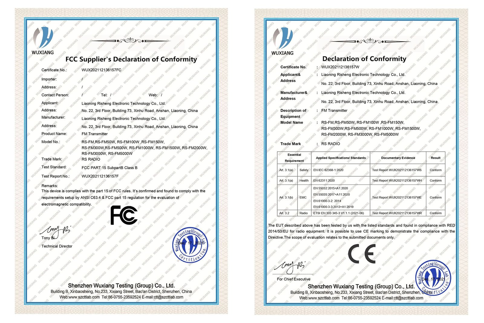
CE Marking (Europe): European EMC Directive and Radio Equipment Directive compliance. Required for legal operation in European Union. RS transmitters are CE marked with comprehensive test documentation.
ITU-R Compliance: International standards providing global technical requirements. RS transmitters meet ITU-R recommendations.
Interference Resolution Experience
I’ve resolved numerous interference complaints. Stations using quality transmitters with clean spectrums rarely cause legitimate interference. When complaints occur, measurements demonstrate compliance defending stations from unwarranted claims.
Stations with marginally compliant transmitters face difficulties. Measurements near compliance limits make interference defense hard. Authorities may require power reduction or additional filtering.
My Recommendation
Request complete RF performance specifications including harmonics, spurious emissions, mask compliance measurements, and frequency stability across temperature range. Verify FCC certification or CE marking for your market. Request third-party test reports. For co-location sites or dense urban markets, specifications should exceed minimum requirements providing safety margins. RS provides complete test reports and certification documentation.
9. Installation Planning: Infrastructure Requirements Beyond the Transmitter
Complete Facility Requirements
I design transmitter facilities understanding successful installations require comprehensive infrastructure planning. Transmitter specifications represent only starting point. Site conditions, power requirements, cooling needs, and physical installation significantly affect project success.
Physical Installation Requirements
Space and Mounting:
RS transmitters use standard 19" rack mounting (100W+ models) or tabletop installation (15-50W models). This simplifies installation in existing equipment rooms.
Typical Dimensions:
- 15-50W: Desktop units, approximately 350mm W x 250mm D x 100mm H
- 100-300W: 2U-3U rack height, 19" width, 400-500mm depth
- 500-1000W: 3U-4U rack height, 19" width, 500-600mm depth
- 1500W+: 4U-6U rack height or floor-standing cabinets
Weight Considerations:
- 15-50W: 5-10 kg
- 100-300W: 15-30 kg
- 500-1000W: 30-60 kg
- 1500W+: 60-150 kg
Clearance Requirements:
- Front clearance: 1 meter for operation and maintenance
- Rear clearance: 300-500mm for cable access and airflow
- Side clearance: 100-200mm for airflow (rack-mount units)
Environmental Requirements
Temperature and Humidity:
| Parameter | RS Specification | Why It Matters |
|---|---|---|
| Operating Temperature | 0°C to +50°C | Covers most indoor/sheltered installations |
| Storage Temperature | -20°C to +60°C | Equipment storage before installation |
| Relative Humidity | 5% to 95% non-condensing | Condensation causes corrosion and failures |
| Altitude | Up to 2000m standard Up to 3000m with derating |
Air density affects cooling |
I’ve installed transmitters in various environments. Climate-controlled transmitter buildings provide optimal conditions. Unheated shelters require verifying low-temperature operation. High-altitude sites need power derating discussion.
Cooling and Ventilation
Transmitter heat dissipation requires proper cooling:
Heat Dissipation Calculation:
Waste Heat = RF Output Power ÷ Efficiency – RF Output Power
Example: 500W transmitter at 65% efficiency
- Total DC power: 770W
- RF output: 500W
- Waste heat: 270W
Cooling Requirements:
| Transmitter Power | Approximate Heat Dissipation | Cooling Air Required |
|---|---|---|
| 100W | 65W | 25 CFM |
| 300W | 160W | 65 CFM |
| 500W | 270W | 110 CFM |
| 1000W | 540W | 215 CFM |
Room Ventilation:
- Small transmitters (<100W): Natural ventilation adequate in temperate climates
- Medium transmitters (100-500W): Mechanical ventilation or air conditioning recommended
- Large transmitters (500W+): Air conditioning or forced ventilation required
I recommend properly sized exhaust fans and fresh air intakes. Low intake/high exhaust placement uses natural thermal circulation. Filter systems prevent dust accumulation.
Electrical Power Requirements
Power Capacity:
Accurate power calculations prevent electrical issues:
| Transmitter Model | RF Output | Typical AC Input Power | Recommended Circuit |
|---|---|---|---|
| 15W | 15W | 35W | 120V 5A |
| 50W | 50W | 100W | 120V 10A |
| 100W | 100W | 180W | 120V 15A |
| 300W | 300W | 520W | 230V 10A |
| 500W | 500W | 900W | 230V 15A |
| 1000W | 1000W | 1,800W | 230V 20A or 3-phase |
RS transmitters up to 1000W operate on single-phase power. 1500W+ models available in single-phase or three-phase configurations depending on regional power standards.
Voltage Compatibility:
RS transmitters feature wide input voltage range (90-260V AC) accommodating various countries without modification. This simplifies international installations and provides tolerance for voltage fluctuations.
Power Quality:
Stable power supply extends transmitter life:
- Voltage stability: ±10% variation acceptable
- Surge protection: Install at service entrance and transmitter connection
- Backup power: UPS for short outages, generator for extended outages
Grounding and Lightning Protection
Station Ground System:
Proper grounding essential for safety, performance, and lightning protection:
- Single-point ground: All equipment connects to common ground bus
- Ground resistance: <10Ω required; <5Ω recommended
- Ground enhancement: Chemical ground rods or extensive radials in poor soil
Lightning Protection:
Critical for transmitter site survival:
- Tower grounding: Extensive ground system at tower base
- Coaxial surge suppressors: On all RF feedlines
- AC power protection: Service entrance and point-of-use suppression
- Data line protection: On all control cables
I’ve seen lightning damage at poorly protected sites. Comprehensive protection systems prevent most damage. Investment in protection is much less than replacement costs.
Special Environment Considerations
Mountain-Top Sites:
- Extreme weather protection
- Enhanced lightning protection (higher strike frequency)
- Difficult access requiring careful spare parts planning
Coastal Sites:
- Salt corrosion protection
- High humidity management
- Hurricane/typhoon structural requirements
Tropical Environments:
- Continuous dehumidification
- Pest control (insects, small animals)
- Rapid vegetation management
Desert Environments:
- Extreme temperature range
- Dust ingress protection
- Solar radiation management
I’ve installed transmitters in all these environments. Each requires specific preparation. Discussing environmental challenges with manufacturer early in planning prevents problems.
Installation Support Services
RS provides comprehensive installation support:
- Complete installation manuals with electrical, cooling, and grounding specifications
- Pre-installation consultation identifying potential issues
- Dimensional drawings and specifications for facility planning
- Electrical load calculations and recommendations
- Cooling requirement calculations
- Grounding system design guidance
- Remote installation support via video call
- On-site installation services available in major markets

My Recommendation
Evaluate complete installation requirements before purchasing. Verify building infrastructure (space, power, cooling, grounding) supports selected transmitter. Calculate total project cost including facility modifications, electrical upgrades, cooling systems, and lightning protection – not just transmitter price. Discuss challenging environments with manufacturer early. RS provides comprehensive pre-installation consultation ensuring successful installation.
10. Manufacturer Support: Your Long-Term Partnership
Beyond the Equipment Transaction
After years supporting broadcast installations globally, I emphasize transmitter selection represents long-term partnership with manufacturer – not simply equipment purchase. Brand reputation and technical support capability often determine project success more than specifications alone.

Evaluating Manufacturer Reputation
Industry Experience and Track Record:
RS manufactures FM transmitters since 2008. Over these years, we’ve continuously improved products based on field experience and customer feedback. We currently support 5000+ transmitters operating across 50+ countries.
I personally joined RS in 2015. I’ve watched the company grow from regional manufacturer to global supplier. This growth came from product quality and customer support – not marketing.
Financial Stability:
Manufacturer financial health affects long-term parts availability and support. Companies struggling financially may cease operations leaving customers without support. Established companies with diverse product lines and global customer base provide support continuity.
Customer References:
I encourage potential customers speaking with existing users. Contact technical staff (not just sales references) asking about:
- Equipment performance and reliability
- Support responsiveness
- Problem resolution
- Parts availability
- Overall satisfaction
RS provides references from similar applications and regions. Real customer experiences matter more than marketing claims.
Regulatory Certifications
Professional transmitters require proper certifications:
| Certification | Coverage | RS Status |
|---|---|---|
| FCC Part 73 | United States | Certified |
| CE Marking | European Union | Certified |
| ISO 9001 | Quality Management | Certified |
| RoHS | Hazardous Substance Restriction | Compliant |
FCC Certification (USA): Part 73 type acceptance verifies compliance with technical standards. Certified transmitters approved for use without individual testing. RS transmitters are FCC Part 73 certified simplifying US installations.
CE Marking (European Union): Demonstrates EMC Directive and Radio Equipment Directive compliance. Required for legal EU operation. RS transmitters are CE marked with comprehensive test documentation.
ISO 9001: Quality management system certification indicating structured manufacturing processes and continuous improvement commitment. RS maintains ISO 9001 certification with annual audits.
Technical Support Infrastructure
Pre-Sales Engineering Support:
Before purchase, I help customers:
- Specify appropriate equipment for applications
- Provide coverage predictions and system design
- Address integration with existing equipment
- Discuss custom configuration options
This consultation prevents mismatched equipment purchases. I’d rather spend time upfront ensuring correct selection than dealing with disappointed customers after delivery.
Installation Assistance:
During installation, RS provides:
- Detailed installation manuals with step-by-step procedures
- Video tutorials covering installation and setup
- Remote installation assistance via WhatsApp or video call
- On-site installation services available (additional cost)
Most customers complete installation successfully with remote guidance. I’ve walked hundreds of customers through installation via video call. Typical installation time: 2-4 hours for experienced technicians.
Ongoing Technical Support:
After installation, ongoing support ensures long-term success:
Support Availability: RS provides 24/7 engineering support via WhatsApp for urgent issues. Business hours support via email and phone for non-urgent questions.
Response Times: Emergency issues receive attention within 1 hour typically. Non-urgent technical questions answered within 24 hours.
Support Methods: WhatsApp (fastest for urgent issues), email, phone, remote desktop assistance when needed.
Support Language: English plus local language support in major markets.
Real Support Example:
Recently a customer in Nigeria experienced sudden transmitter failure at 2 AM local time. He contacted me via WhatsApp. Despite time difference, I responded within 20 minutes. Through video call, I diagnosed failed cooling fan. He had spare fan in stock (following my recommendation). I guided replacement via video. Total downtime: 45 minutes.
This kind of support only works with manufacturer committed to customer success and engineer experienced with products.
Spare Parts Availability
Parts Inventory: RS maintains comprehensive spare parts inventory at headquarters. Critical parts ship within 24-48 hours of order.
Global Delivery: We ship spare parts worldwide. Typical delivery times:
- Asia: 3-5 days
- Americas: 4-7 days
- Europe: 5-8 days
- Africa: 5-10 days
Parts Availability Commitment: RS commits to 15-year parts availability for all transmitter models. Even discontinued models receive parts support during this period.
Parts Pricing: Transparent pricing and availability information. No surprise costs or unavailable parts years after purchase.
Warranty Coverage
RS Warranty Terms:
| Coverage | Standard Industry | RS Warranty |
|---|---|---|
| Duration | 1-2 years | 5 years |
| Coverage | Parts only | Comprehensive parts and labor |
| Shipping | Customer pays | RS pays for warranty replacements |
| Service | Return to factory | Advance replacement available |
5-Year Comprehensive Warranty: Industry-leading coverage demonstrating product confidence. Covers parts, labor, and shipping for warranty repairs.
Advance Replacement Program: For critical applications, RS ships replacement units before receiving failed units. This minimizes downtime for stations requiring maximum uptime.
Warranty Process: Simple registration and claim procedures. Most warranty issues resolved through component replacement shipped directly to customers.
%(Warranty service)FM transmitter warranty coverage
Software and Firmware Support
Firmware Updates: RS provides free firmware updates for product lifetime. Updates add features, fix bugs, and improve performance.
Remote Update Capability: Network-connected transmitters support secure remote firmware updates. I can update transmitter firmware remotely simplifying deployment.
Feature Enhancements: RS commits to product improvement. Firmware updates often add functionality to existing transmitters at no cost.
Long-Term Support: Firmware support continues throughout product operational lifetime (10-15 years minimum).
Value-Added Services
Beyond basic support, RS offers:
System Design: Complete broadcast system design beyond just transmitters – antenna systems, combiners, STL links, complete station planning.
Frequency Coordination: Assistance with frequency coordination and licensing applications.
Project Management: Turnkey project delivery including all equipment procurement and integration.
Training Services: Comprehensive operational and maintenance training via video or on-site.
Maintenance Contracts: Optional preventive maintenance programs with priority support.
Total Cost of Ownership Analysis
Quality manufacturer support affects TCO significantly:
Lower TCO with Good Support:
- Faster problem resolution reduces downtime
- Remote support reduces service call costs
- Good documentation reduces troubleshooting time
- Readily available parts minimize downtime
- Firmware updates extend equipment life
Higher TCO with Poor Support:
- Extended downtime waiting for support response
- Expensive emergency service calls
- Difficult troubleshooting without good documentation
- Unavailable parts forcing premature replacement
- No product improvements over lifetime
How RS Delivers Value
- 15+ years FM transmitter manufacturing experience
- 5000+ transmitters operating globally
- FCC and CE certified products
- ISO 9001 quality management
- 24/7 technical support via WhatsApp
- Typical 1-hour response for urgent issues
- Global spare parts delivery 3-10 days
- 15-year parts availability commitment
- 5-year comprehensive warranty
- Free lifetime firmware updates
- Complete documentation and training
- Pre-sales engineering consultation
- Post-sales technical support
My Personal Commitment
As RS technical engineer, I’m personally committed to customer success. My contact information goes to every customer. I respond to WhatsApp messages day or night for urgent issues. I’ve guided installations in over 50 countries via video call. Your success is my success.
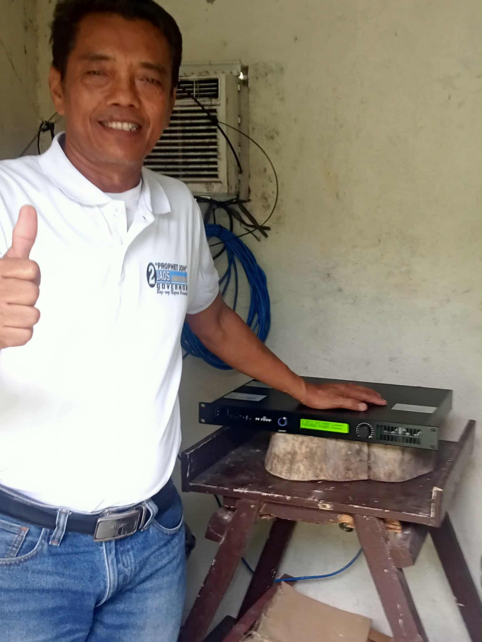
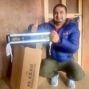
This isn’t marketing talk. This is how I actually work. Ask RS customers in Philippines, Kenya, USA, Mexico, or anywhere we operate. They’ll tell you about real support experiences.
Recommendation
Evaluate manufacturer support as carefully as technical specifications. Consider:
- Company history and stability
- Customer references from similar applications
- Certifications and compliance documentation
- Technical support availability and response times
- Spare parts availability and delivery times
- Warranty terms and service process
- Long-term support commitment
Purchase price is one-time cost. Support quality affects success over entire 10-15 year equipment life. Choose manufacturers committed to long-term customer relationships, not just sales transactions.
Summary: Making Your Transmitter Selection Decision
After discussing these ten critical buying facts, let me summarize what matters most:
Key Decision Factors:
-
Coverage Planning: Specify system requirements, not just transmitter power. Professional coverage analysis ensures appropriate equipment selection.
-
System Integration: Verify compatibility with existing studio equipment, audio processors, and automation systems.
-
Audio Quality: Demand specifications meeting or exceeding professional broadcast standards. Margins matter.
-
Reliability: Evaluate protection systems, redundancy options, and actual MTBF data. Calculate downtime costs.
-
Energy Efficiency: Calculate 10-year total cost of ownership including energy costs. Efficient transmitters pay for themselves.
-
Maintainability: Modular design and good diagnostics minimize downtime and maintenance costs.
-
Remote Monitoring: Non-negotiable for unattended sites. Comprehensive monitoring prevents problems and speeds resolution.
-
Spectrum Purity: Margins above regulatory requirements ensure long-term compliance and interference-free operation.
-
Installation Planning: Evaluate complete infrastructure requirements including power, cooling, and grounding.
-
Manufacturer Support: Long-term partnership matters more than initial price. Support quality affects success throughout equipment life.
Total Cost of Ownership Perspective
Don’t select transmitters based solely on purchase price. Consider:
- Initial equipment cost (20-40% of TCO)
- 10-year energy costs (40-50% of TCO)
- Maintenance and downtime costs (20-30% of TCO)
- Support and parts availability
Professional transmitters with higher initial costs often deliver lower TCO through efficiency, reliability, and support quality.
My Final Advice
I’ve supported thousands of broadcast installations worldwide. Successful projects share common characteristics:
- Thorough planning before equipment purchase
- Realistic coverage analysis and expectations
- Proper infrastructure preparation
- Quality equipment from reputable manufacturers
- Comprehensive technical support
Conversely, problem projects typically result from:
- Inadequate planning
- Unrealistic coverage expectations
- Infrastructure shortcuts
- Selecting based solely on lowest price
- Poor manufacturer support
Take time in equipment selection. Ask questions. Request demonstrations. Speak with existing customers. Verify certifications. Understand total costs.
I’m here to help. Contact me with questions about your broadcast project. I’ll provide honest advice even if RS equipment isn’t the best fit for your application. My goal is your broadcasting success.