Top 10 Common FM Signal Problems and How to Fix Them
I work as a technical engineer at RS supporting community radio stations, religious broadcasters, and commercial stations. These organizations operate 50W-3000W FM transmitters daily. Maybe you installed your transmitter months ago but coverage disappoints you. Listeners complain about noise, dropouts, or unstable signals. I troubleshoot these problems weekly helping stations identify root causes and implement lasting solutions. This guide addresses the ten most common signal problems I encounter with broadcast-grade FM transmitters.
Note: This article targets professional FM broadcast transmitters (50W-10000W) serving community stations, churches, campuses, and commercial broadcasters. I exclude car FM transmitters, pocket transmitters, and low-power hobby devices under 15W.

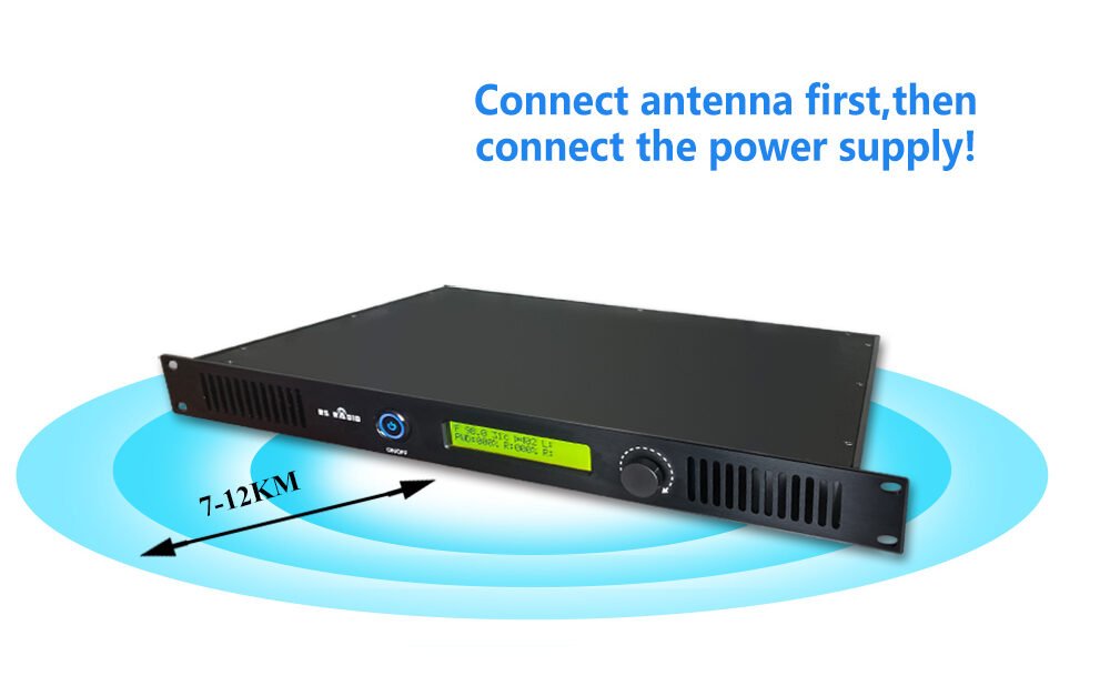
1. Coverage Falls Short of Expectations
Symptom: You purchased a 100W transmitter expecting 10 km coverage based on specifications. Real-world coverage barely reaches 5 km. Listeners at expected distances report weak or no signal.
Technical Causes:
Actual Output Power Lower Than Rated: Some manufacturers rate transmitters at peak power rather than continuous power. A "100W" transmitter might deliver only 70W continuous output. I measure customer transmitters finding 20-30% power deficits regularly.
Antenna System Losses: Feedline losses waste transmitter power as heat. Poor quality coaxial cable loses 30-40% of power. A 100W transmitter with bad cable delivers 60-70W to antenna. Improper connectors add additional losses.
Antenna Placement Too Low: Antenna height affects coverage dramatically. A 100W transmitter at 20m height covers much less than same transmitter at 40m height. Every 10 meters of additional height increases coverage radius 15-20%.
Terrain Obstacles: Buildings, hills, and vegetation block signals. Urban environments reduce coverage 30-40% compared to rural areas. Manufacturers quote coverage for ideal flat terrain rarely matching real conditions.
How to Fix:
-
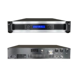
Measure Actual Output Power: Use calibrated RF power meter measuring transmitter output directly. RS transmitters deliver rated power ±5%. If your transmitter shows significant deficit, it needs repair or replacement.
-
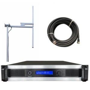
Calculate Feedline Loss: Check cable type and length. Replace any cable smaller than 1/2" (for 100W+) or showing weather damage. Proper cable maintains >90% efficiency.
-
Maximize Antenna Height: Raising antenna produces bigger coverage improvement than increasing transmitter power. A 100W transmitter at 50m height outperforms 300W at 30m height. Invest in antenna elevation before buying more power.
-
Conduct Site Survey: Drive your coverage area with FM radio measuring signal strength at different locations. Identify weak zones and determine if adding antenna height or power solves the problem.
When to Upgrade Equipment:
If your transmitter delivers significantly less than rated power after confirming proper antenna system, the transmitter needs replacement. RS transmitters include adjustable power output in 0.1W steps – you verify exact output power on digital display. If you started with 100W and need genuine 300W coverage, RS 300W ($1,339) delivers reliable output with 5-year warranty protection.
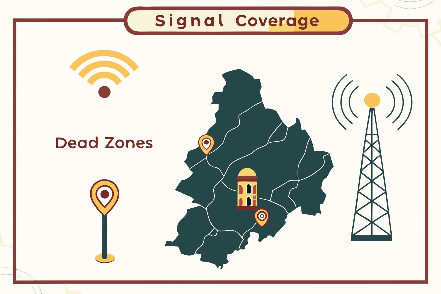
2. Uneven Coverage with Dead Zones
Symptom: Signal reaches some directions well but specific areas show no reception despite being within expected coverage radius. North side works perfectly while south side shows dead zones. Buildings or hills create shadow areas.
Technical Causes:
Omnidirectional Antenna Pattern Disruption: Nearby metal structures distort antenna radiation patterns. Towers, buildings, and large metal objects near antenna create reflections changing coverage pattern. Antenna might radiate strongly in some directions while creating nulls in others.
Terrain Shielding: Hills and valleys block FM signals. Radio waves travel in straight lines – anything blocking line of sight reduces signal strength. Mountainous terrain creates pronounced shadow zones.
Antenna Polarization Issues: Vertical antennas work best with vertical receiving antennas. Mixed polarization reduces received signal strength. Most car radios use vertical antennas while home systems vary.
Insufficient Gain in Problem Directions: Omnidirectional antennas radiate equally in theory but real-world installations show variations. Local environment affects different directions differently.
How to Fix:
-
Antenna Relocation Survey: Test antenna at different positions on same tower or building. Moving antenna 5-10 meters sometimes eliminates nulls caused by reflections.
-
Increase Antenna Height: Higher placement clears more obstacles improving coverage uniformity. Height helps more than any other single factor.
-
Switch to Directional Antenna: If coverage needed mainly in one direction, directional antenna focuses power toward target area. This doubles or triples effective coverage in desired direction.
-
Add Fill-In Translators: Severe shadow zones might require secondary low-power transmitters (translators) rebroadcasting your signal. A 50W fill-in transmitter covers dead zones economically.
-
Use Higher Gain Antenna: Multi-bay antennas provide gain by focusing energy horizontally. A 4-bay antenna provides 6 dBd gain effectively doubling transmitter power.
When to Upgrade Equipment:
Dead zones from terrain or buildings rarely fix with transmitter changes alone. However, if you operate 50-100W and face severe shadowing, upgrading to 300-500W combined with better antenna placement might overcome obstacles. RS transmitters include remote monitoring – you adjust power levels testing coverage without on-site visits. A station in Kenya solved dead zone problems by upgrading from RS 100W ($650) to RS 300W ($1,339) and raising antenna from 25m to 45m height.
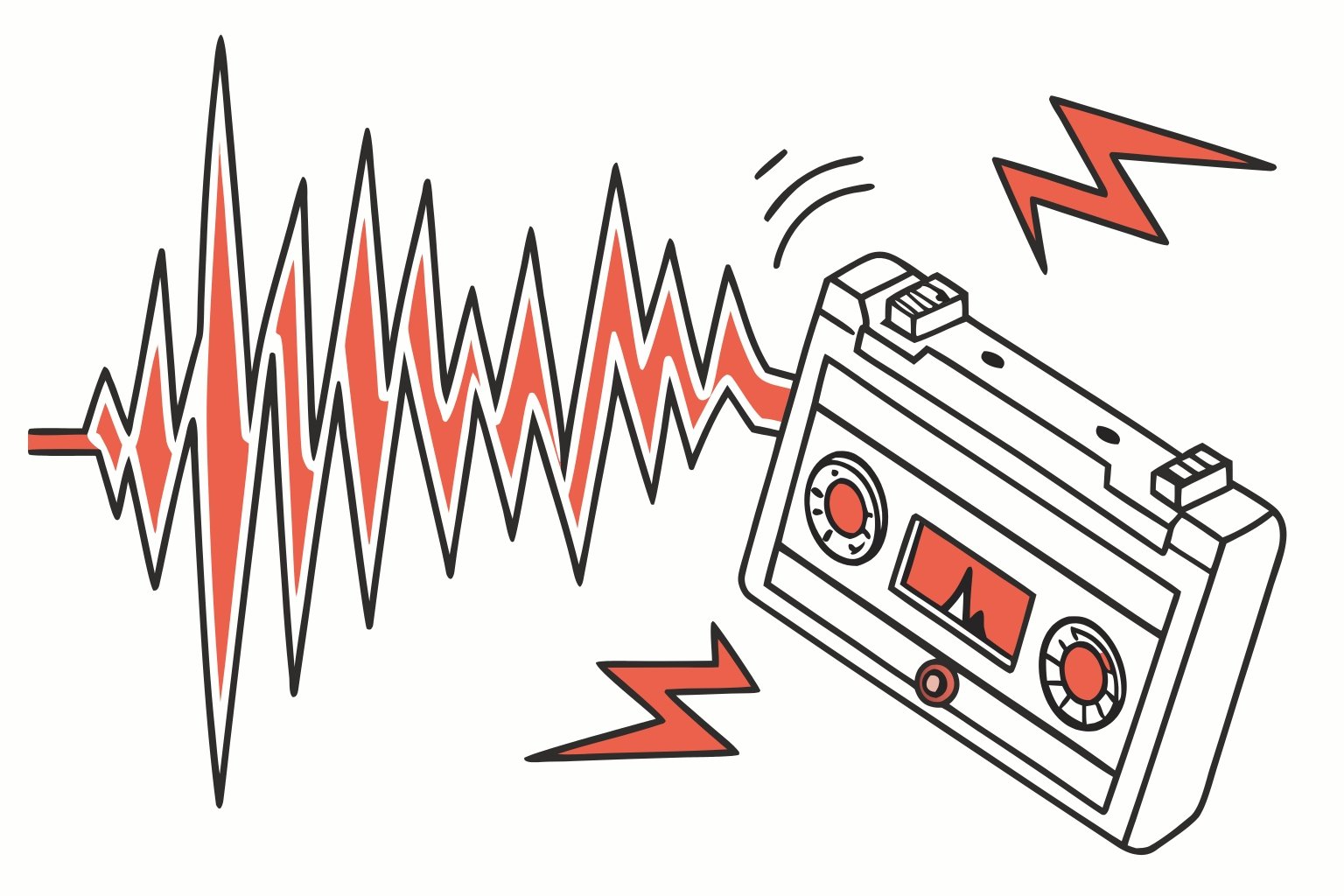
3. Excessive Noise and Static
Symptom: Background hiss, static, or noise audible during quiet program moments. Listeners complain about poor audio quality despite clean source audio. Noise levels vary but constantly present.
Technical Causes:
Poor Signal-to-Noise Ratio in Transmitter: Budget transmitters show 50-60 dB S/N ratio introducing audible hiss. Professional transmitters maintain 70+ dB S/N ratio. RS transmitters deliver 75 dB signal-to-noise ratio – listeners hear clean audio without background noise.
Electrical Interference in Audio Chain: Power supply noise, ground loops, and electromagnetic interference contaminate audio before reaching transmitter. Switching power supplies, fluorescent lights, and electrical equipment generate noise picked up by audio cables.
Modulation Level Too Low: Under-modulated FM signals force listeners to increase volume amplifying receiver noise. Proper modulation (±75 kHz deviation for 100% modulation) maximizes signal strength relative to noise.
Transmitter Audio Circuit Design: Analog audio circuits age and drift. Component tolerances add noise. DSP digital audio processing eliminates analog circuit noise maintaining consistent low-noise performance.
RF Interference from Nearby Equipment: Computers, LED displays, and digital equipment generate RF interference demodulating in audio circuits. Poor shielding allows interference entering transmitter audio stages.
How to Fix:
-
Measure Transmitter S/N Ratio: Professional stations test S/N ratio annually. If your transmitter shows deteriorating S/N ratio (common in aging equipment), audio circuits need servicing or transmitter needs replacement.
-
Clean Up Audio Chain: Use balanced XLR connections throughout audio chain. Separate audio cables from AC power cables. Connect all equipment to common ground point eliminating ground loops. Replace any unbalanced connections with balanced alternatives.
-
Optimize Modulation Level: Adjust input levels achieving 90-100% modulation on peaks. RS transmitters include built-in AGC (Automatic Gain Control) maintaining optimal modulation automatically. Most problems from under-modulation rather than over-modulation.
-
Filter AC Power: Install RF filters on AC power lines. Use shielded power cables. Consider UPS power supply providing clean, filtered power to entire broadcasting chain.
-
Shield Audio Equipment: Ensure all audio equipment properly grounded with metal chassis connected to ground. Replace any equipment with plastic cases showing RF susceptibility.
When to Upgrade Equipment:
If your transmitter shows inherently high noise floor (>60 dB S/N ratio), upgrading eliminates noise problems permanently. RS DSP transmitters maintain 75 dB S/N ratio from day one through entire service life. Digital processing eliminates analog component aging and drift. A religious broadcaster in Nigeria replaced noisy 10-year-old transmitter with RS 300W achieving dramatic audio quality improvement listeners commented on immediately.
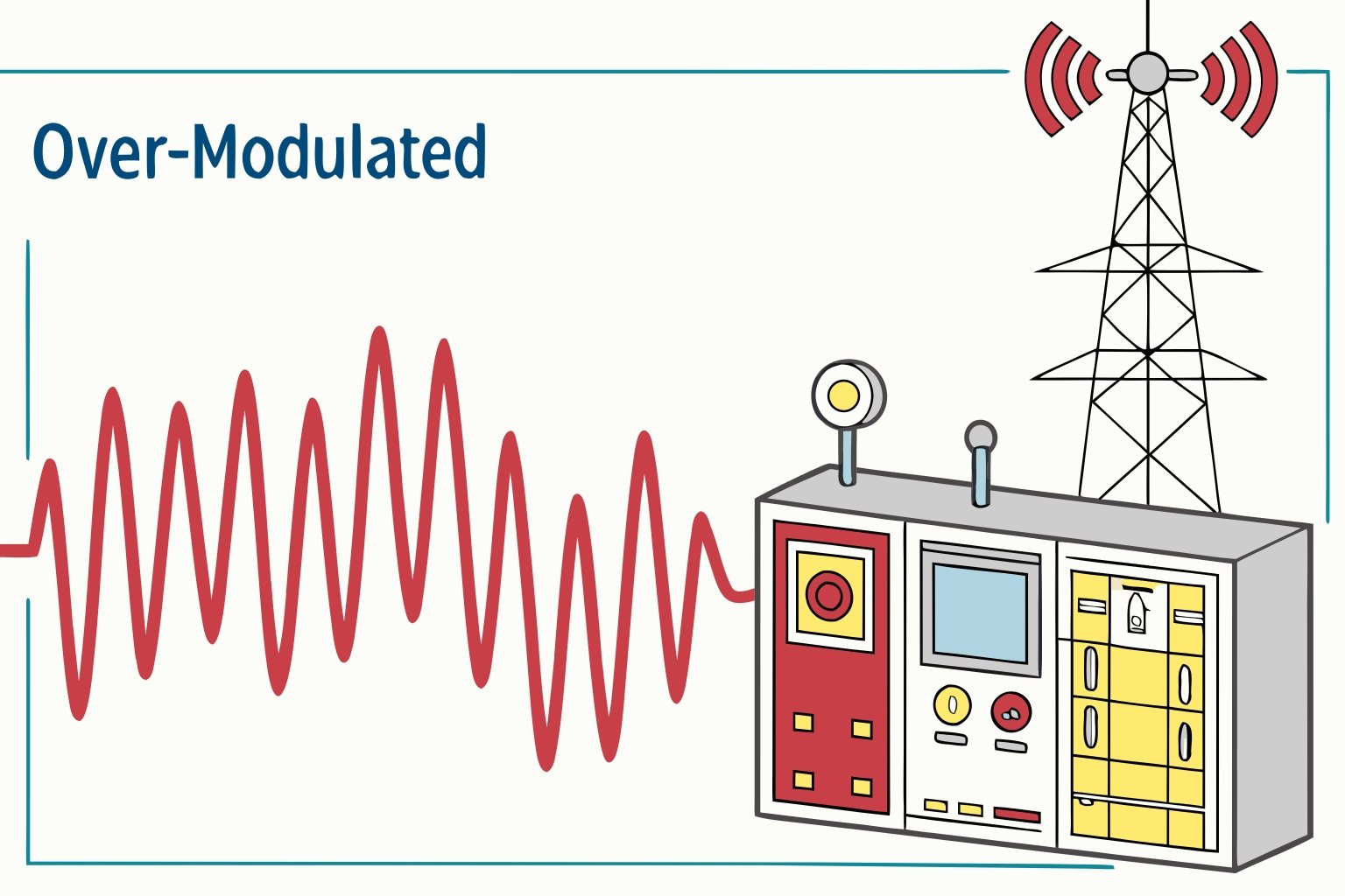
4. Audio Distortion and Over-Modulation
Symptom: Audio sounds distorted, harsh, or clips during loud passages. Listeners describe "crunchy" or "fuzzy" sound. Bass sounds muddy. High frequencies harshness. Volume inconsistent with sudden loud bursts.
Technical Causes:
Over-Modulation (Deviation >±75 kHz): Excessive input levels drive transmitter beyond ±75 kHz maximum deviation. Over-modulated signals distort and create splatter interference on adjacent frequencies. Regulators cite stations for over-modulation violations.
Incorrect Pre-emphasis Settings: USA and Philippines use 75 μs pre-emphasis while Europe and most other countries use 50 μs. Mismatched pre-emphasis makes audio sound excessively bright or dark causing perceived distortion.
Audio Limiter Malfunction: Limiters prevent over-modulation by restricting peak levels. Failed or improperly adjusted limiters allow excessive levels reaching transmitter.
Transmitter Audio Circuit Distortion: Cheap transmitters use low-quality audio circuits with 0.5-1.0% THD (Total Harmonic Distortion). Professional transmitters maintain <0.05% THD. RS transmitters achieve 0.02% THD – cleaner than most audio sources feeding them.
Clipper Circuit Over-Compression: Some stations use aggressive audio processing creating over-compressed, distorted sound competing for loudness. Excessive clipping creates listener fatigue.
How to Fix:
-
Reduce Input Levels: Decrease audio source output or transmitter input gain until modulation meter shows peaks at 90-100%. Never exceed 100% modulation continuously.
-
Verify Pre-emphasis Settings: Check transmitter pre-emphasis matches regional standard. RS transmitters offer 0, 50 μs, and 75 μs selectable pre-emphasis matching any location worldwide.
-
Test with Clean Audio Source: Connect high-quality audio source (CD player or computer with lossless audio) directly to transmitter. If distortion disappears, problem lies in audio chain before transmitter. If distortion persists, transmitter needs attention.
-
Adjust Audio Processing: If using external audio processor, reduce compression and limiting. Start with conservative settings then increase gradually. Professional sound comes from clean audio, not maximum loudness.
-
Measure THD (Total Harmonic Distortion): Use audio analyzer measuring transmitter THD. If THD exceeds 0.1%, transmitter audio circuits need repair or replacement.
When to Upgrade Equipment:
Transmitters with inherently high distortion (>0.1% THD) or inadequate limiting protection require replacement. RS transmitters include DSP audio processing maintaining 0.02% THD and comprehensive AGC preventing over-modulation automatically. Built-in limiters protect against occasional excessive levels while preserving audio quality. A commercial station in Philippines upgraded from aging transmitter with 0.8% THD to RS 1000W achieving dramatic audio quality improvement earning positive listener feedback.
5. Frequency Instability and Drift
Symptom: Listeners complain your station "drifts" off frequency. They must retune periodically finding your signal. Digital radios with RDS show incorrect frequency. Measured frequency varies by several kHz daily.
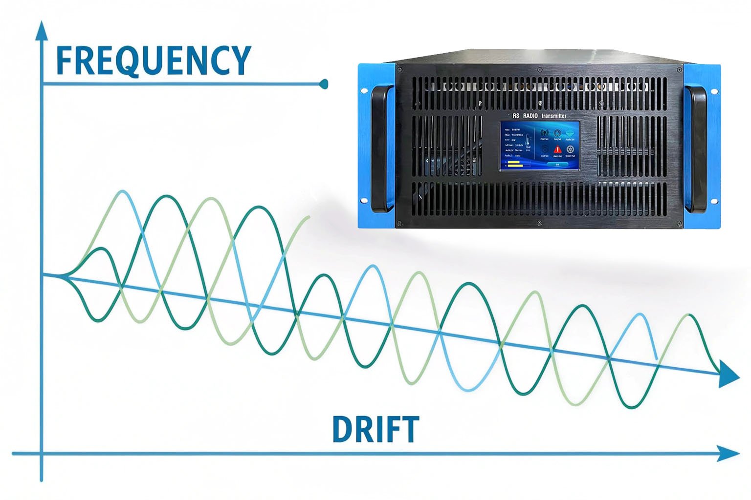
Technical Causes:
Analog Oscillator Design: Budget transmitters use analog LC oscillators drifting ±2-5 kHz with temperature changes. Morning to afternoon temperature swings move frequency significantly. Aging components accelerate drift.
Poor Temperature Compensation: Transmitters operating in uncontrolled environments experience wide temperature variations. Without proper compensation, frequency shifts as transmitter heats up during operation.
Crystal Oscillator Quality: Reference crystal quality determines frequency stability. Low-quality crystals drift more than precision crystals. Crystal aging increases drift over years.
No PLL Frequency Synthesis: Modern professional transmitters use PLL (Phase-Locked Loop) digital frequency synthesis locking carrier to stable reference. PLL maintains ±200 Hz accuracy regardless of temperature or aging.
How to Fix:
-
Measure Frequency Drift: Use precision frequency counter monitoring carrier frequency over 24 hours. Professional transmitters maintain ±500 Hz throughout operating temperature range. If your transmitter drifts >±2 kHz, it needs service or replacement.
-
Control Transmitter Room Temperature: Install air conditioning maintaining stable temperature. This helps but doesn’t eliminate drift in analog oscillator designs.
-
Recalibrate Frequency: Some transmitters allow manual frequency adjustment compensating drift. This temporary fix – transmitter continues drifting requiring periodic recalibration.
-
Upgrade to PLL Transmitter: PLL digital synthesis eliminates frequency drift permanently. RS transmitters use PLL maintaining ±200 Hz accuracy across full operating temperature range (-10°C to +45°C). Listeners never retune – your frequency stays precisely where set.
When to Upgrade Equipment:
Frequency instability indicates fundamental design limitations. Analog oscillator transmitters inevitably drift. Only PLL digital synthesis provides reliable frequency stability. Regulatory authorities increasingly enforce tight frequency tolerance (±2000 Hz typical limit). Transmitters drifting beyond limits risk violation citations and fines.
RS transmitters include PLL digital frequency synthesis as standard feature across all power levels (15W-10000W). Frequency stays stable through temperature changes, aging, and voltage fluctuations. A community station in Ghana eliminated chronic frequency complaints by upgrading to RS 300W with PLL stability. Listeners no longer retune – digital radios lock station name and frequency perfectly.
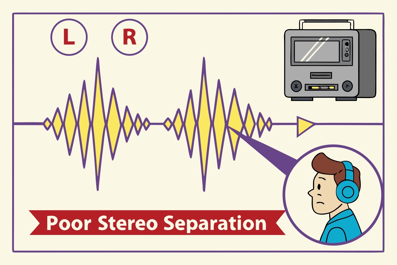
6. Stereo Separation Problems
Symptom: Stereo indicator light on receivers flickers on and off. Stereo image collapses to mono intermittently. Left and right channels imbalanced. Some receivers show stereo while others show mono from same signal.
Technical Causes:
Poor Stereo Encoder Quality: Budget stereo encoders show 30-40 dB separation between channels. Professional encoders maintain 50+ dB separation. Low separation creates muddy stereo image collapsing toward mono.
19 kHz Pilot Tone Instability: Stereo encoding requires stable 19 kHz pilot tone. Unstable pilot causes receivers dropping in and out of stereo mode. Receivers detect pilot tone to enable stereo decoding.
L-R (Left minus Right) Signal Weakness: Stereo encoding creates L+R and L-R signals. Weak L-R component reduces separation. Listeners hear mostly mono with slight stereo effect.
Phase Issues in Audio Source: If left and right channels arrive at transmitter with phase differences, stereo encoding degrades. Phase problems create narrow stereo image or false separation.
Composite MPX Signal Problems: External stereo generators output composite MPX signals containing stereo-encoded audio plus pilot tone. Poor quality MPX signals or cable connections degrade stereo performance.
How to Fix:
-
Measure Stereo Separation: Use modulation monitor with stereo decoder measuring L-R separation. Professional transmitters maintain 50-60 dB separation. Below 40 dB indicates encoder problems.
-
Check Pilot Tone Level: Pilot tone should measure ±10% deviation (±7.5 kHz). Too low – receivers don’t detect stereo. Too high – wastes modulation headroom causing distortion.
-
Verify Input Balance: Test left and right input levels match within ±0.5 dB. Imbalanced inputs create false stereo image confusing listeners.
-
Test Mono Compatibility: Listen to your station in mono mode. Good stereo encoding sounds natural in mono. Poor encoding creates phasey, hollow sound in mono.
-
Inspect MPX Connections: If using external processor with MPX output, check cable quality and connections. MPX signals sensitive to cable quality – use shielded cable rated for composite audio.
When to Upgrade Equipment:
Transmitters with built-in stereo encoders showing <40 dB separation provide poor stereo experience. RS transmitters include professional DSP stereo encoders maintaining 60 dB separation – listeners hear distinct left and right channels with excellent imaging. Stereo remains stable regardless of program content or modulation levels.
RS supports both internal stereo encoding and external MPX composite input. Professional stations using external audio processors connect via MPX input bypassing internal encoder. This configuration delivers maximum audio quality and processing flexibility.
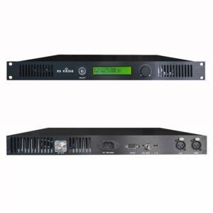
A campus station in Philippines complained about stereo instability with their budget transmitter. After upgrading to RS 50W ($488), students immediately noticed improved stereo imaging and stable stereo decoding across all receivers.
7. Time-Specific Signal Problems
Symptom: Signal quality varies by time of day. Morning broadcasts sound perfect but evening shows increased noise or reduced coverage. Specific hours show complete signal loss. Weather-dependent problems appearing during rain or high winds.

Technical Causes:
Electrical Power Quality Variation: Utility power quality deteriorates during peak demand hours (evening). Voltage drops and increased electrical noise affect transmitter performance. Industrial equipment cycling on/off creates interference.
Temperature-Related Protection Activation: Transmitters automatically reduce power or shut down when overheating. Afternoon heat combined with transmitter heat accumulation triggers thermal protection. Inadequate ventilation exacerbates afternoon overheating.
Scheduled Interference: Other stations broadcasting only during specific hours create interference. Commercial stations operating daytime only don’t interfere with your evening broadcasts but dominate frequency during their hours.
Antenna System Thermal Expansion: Metal antenna elements and coaxial cables expand with temperature. Severe temperature cycling changes antenna tuning and feedline characteristics affecting signal quality.
Atmospheric Propagation Changes: Temperature inversions (especially evening and overnight) extend FM coverage unexpectedly. Your signal travels farther during inversions encountering distant stations on same frequency creating interference.
How to Fix:
-
Monitor Power Quality: Install voltage monitor recording AC power quality 24 hours. If voltage drops >10% during problem periods, install voltage regulator or UPS system maintaining stable power.
-
Improve Cooling: Clean air intake filters. Verify cooling fans operating properly. Increase transmitter room air conditioning capacity. RS transmitters include variable-speed fans adjusting to thermal load automatically. Over-temperature protection activates at 60°C preventing damage but reducing power.
-
Identify Interference Sources: Scan frequency during different times identifying competing stations. Contact interfering stations coordinating frequency usage or adjusting power levels. Regulatory authorities mediate interference disputes.
-
Schedule Maintenance During Problem Hours: If overheating occurs afternoon only, service transmitter before afternoon broadcasts. Consider installing transmitter in air-conditioned environment maintaining stable temperature.
-
Log Environmental Conditions: Record temperature, humidity, and signal quality measurements correlating problems with environmental factors. This data helps identify root causes.
When to Upgrade Equipment:
Transmitters shutting down from thermal protection indicate inadequate cooling design. RS transmitters operate reliably in ambient temperatures up to 45°C. Below 35°C ambient, transmitters run at full power continuously without thermal protection activation. Forced-air cooling with variable-speed fans adapts to thermal load.
If power quality problems persist despite UPS installation, transmitter power supply may lack adequate regulation. RS transmitters include wide-range power supplies (AC 180-260V) tolerating voltage variations without affecting output power or audio quality.
A church in Kenya experienced afternoon shutdowns during hot season. After investigating, I found transmitter room temperature reaching 48°C. Installing air conditioning and upgrading to RS 100W with improved thermal design eliminated shutdowns completely.
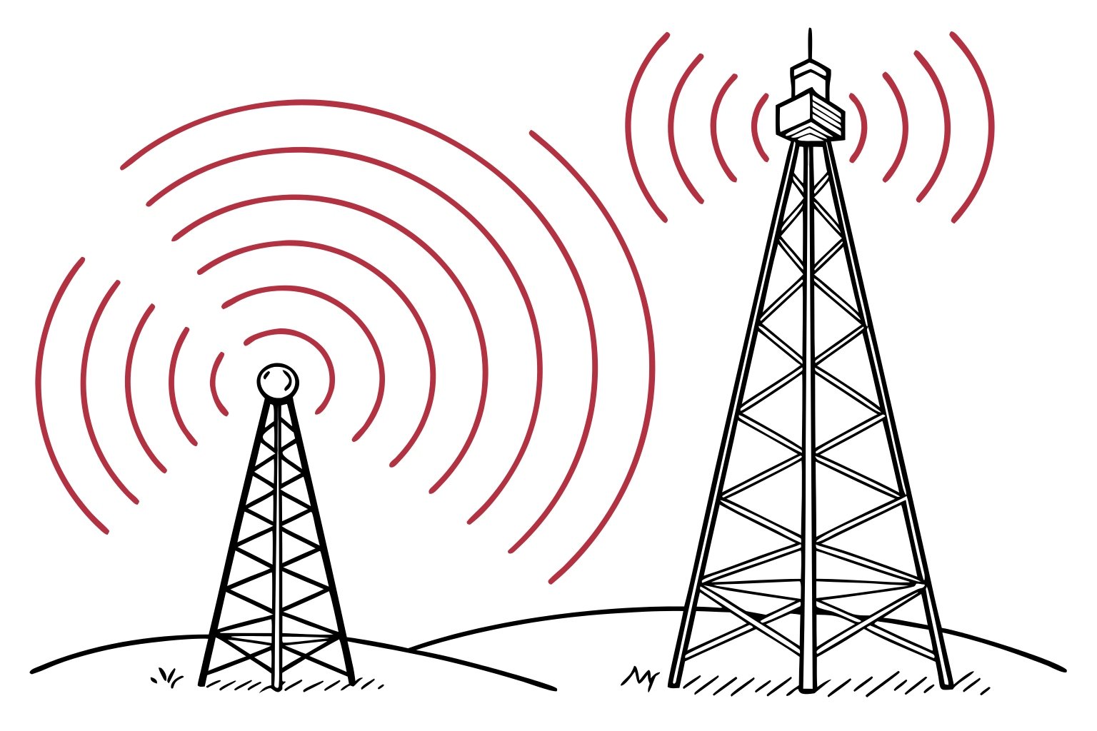
8. Interference from Adjacent Stations
Symptom: Another station’s audio bleeds into yours. Listeners hear two stations simultaneously. Strong local station overpowers your signal. Interference appears only in specific locations. Heterodyne whistle audible on your frequency.
Technical Causes:
Insufficient Frequency Separation: FM stations require minimum frequency separation avoiding interference. Too-close frequencies create adjacent channel interference. Standard practice requires ±400 kHz separation from strong stations.
Transmitter Spurious Emissions: Poor quality transmitters radiate spurious signals on adjacent frequencies. These spurious emissions interfere with nearby stations. Regulatory specifications limit spurious emissions -60 dBc or better.
Receiver Selectivity Problems: Some older or cheap receivers lack adequate selectivity separating adjacent stations. Strong local stations overload receiver front ends causing desensitization and interference.
Intermodulation Products: Multiple strong signals mixing in nonlinear circuits (transmitter, antenna system, or receiver) create intermodulation products appearing on third frequencies. Third-order products calculated as 2×f₁ – f₂ or 2×f₂ – f₁.
Co-Channel Interference: Two stations using identical frequency interfere when coverage areas overlap. This occurs accidentally from frequency mismanagement or intentionally from pirate stations.
How to Fix:
-
Conduct Frequency Survey: Scan FM band identifying all strong signals in your area. Select frequency with maximum separation from existing stations. Coordinate with regulatory authority ensuring proper frequency allocation.
-
Measure Transmitter Spurious Emissions: Professional stations test spurious emissions annually using spectrum analyzer. If your transmitter shows excessive spurious emissions (>-50 dBc), it requires servicing or replacement.
-
Reduce Transmitter Power: If your signal overpowers adjacent stations, reduce power to minimum necessary for coverage. RS transmitters offer 0.1W step power adjustment – precisely set power avoiding interference while maintaining coverage.
-
Add Bandpass Filtering: Install cavity filter or bandpass filter between transmitter and antenna. Filters suppress out-of-band emissions improving frequency cleanliness. This helps both reducing interference you cause and receiving interference.
-
Contact Regulatory Authority: Report interference to communications authority. They mediate disputes, enforce frequency allocations, and take action against violators. Document interference with recordings and measurements.
When to Upgrade Equipment:
Transmitters lacking adequate harmonic suppression and spurious emission filtering cause interference to other services. Professional transmitters include comprehensive filtering maintaining clean output signals.
RS transmitters meet FCC Part 73 and CE standards for spurious emissions and harmonic suppression. Harmonic suppression exceeds -60 dBc. Spurious emissions stay well below regulatory limits preventing interference to adjacent channels and other services.
A commercial station in Philippines faced interference complaints from adjacent channel station. Measurements showed their budget transmitter generating excessive spurious emissions. After upgrading to RS 500W ($1,560), spurious emissions decreased 15 dB eliminating complaints. Regulatory authority cleared them for continued operation.
9. High Power with Poor Results
Symptom: You upgraded from 100W to 500W expecting 5× coverage area increase. Actual improvement disappoints – coverage expanded only slightly. Listeners report marginal improvement. Investment in higher power didn’t deliver expected returns.

Technical Causes:
Antenna System Limitations: Antenna and feedline designed for 100W show significant losses at 500W. A 100W feedline losing 3W (3% loss, 0.13 dB) loses 50W at 500W (10% loss, 0.46 dB). Poor antenna system wastes expensive power as heat.
Coverage Physics (Inverse Square Law): Doubling power increases coverage radius only 40% (not 100%). Increasing from 100W to 500W extends coverage radius approximately 2× but covers 4× area. Listeners expect dramatic improvement but physics limits actual gains.
Existing Coverage Already Limited by Terrain: If terrain obstacles limit coverage, additional power can’t overcome physical blockages. Hills, buildings, and valleys attenuate signals regardless of power. Antenna height helps more than power in these situations.
Interference-Limited Rather than Power-Limited: When other stations limit your coverage (interference) rather than weak signal, more power doesn’t help. You need better frequency coordination or cleaner signal.
Antenna Gain Mismatch: High-power transmitter connected to low-gain antenna wastes potential. A 500W transmitter with 1-bay dipole (0 dBd gain) covers less than 300W with 4-bay antenna (6 dBd gain).
How to Fix:
-
Measure Actual System Efficiency: Use RF power meter measuring power at transmitter output and power reaching antenna after feedline. Losses exceeding 10% indicate poor feedline quality requiring replacement.
-
Upgrade Antenna System First: Before increasing transmitter power, maximize antenna height and gain. A 100W transmitter with proper antenna system outperforms 500W with poor antenna. Height matters more than power.
-
Calculate Effective Radiated Power (ERP): ERP = Transmitter Power × Feedline Efficiency × Antenna Gain. This number determines actual coverage. Two stations with different transmitter powers but same ERP provide equal coverage.
-
Conduct Coverage Measurements: Drive coverage area before and after power increase measuring actual signal strength improvement. If improvement disappoints, antenna system needs attention not more power.
-
Consider Alternative Solutions: Translators (secondary transmitters) covering shadow zones provide better return than raw power increase. Directional antennas focus power toward target areas doubling effective coverage in desired directions.
When to Upgrade Equipment:
If your antenna system properly designed and installed but coverage still insufficient, higher power helps. However, upgrade antenna system simultaneously with transmitter ensuring system handles increased power efficiently.
RS transmitters include precise power adjustment (0.1W steps) and accurate power metering. You verify actual output power matching your investment. Built-in SWR monitoring ensures antenna system efficiency – high SWR indicates losses wasting power.
A community station invested in RS 300W upgrade from 100W without improving antenna system. Coverage improved minimally. After I recommended antenna system upgrade (better feedline and 2-bay antenna), coverage doubled dramatically. The lesson: antenna system efficiency determines actual performance regardless of transmitter power.
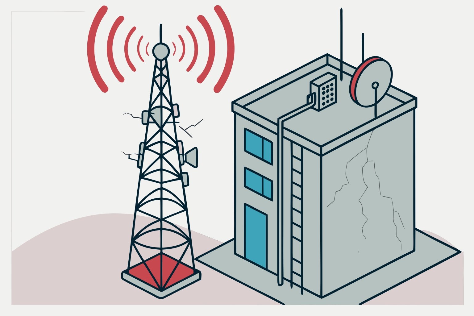
10. Progressive Performance Degradation
Symptom: Transmitter worked perfectly initially but performance gradually declined over months. Automatic shutdowns increase in frequency. Output power decreases requiring manual adjustment. Coverage shrinks slowly over time. Heat becomes excessive during operation.
Technical Causes:
Dust Accumulation Blocking Cooling: Dust blocks air intake filters and accumulates on internal components. Restricted airflow causes overheating. Thermal stress ages components faster creating cascading failures.
Component Aging (Capacitors, Transistors): Electrolytic capacitors dry out over years losing capacity. Power amplifier transistors degrade from thermal cycling. RF circuits drift from component aging changing tuning and efficiency.
Oxidation and Corrosion: Humidity causes oxidation on connectors and circuit boards. Oxidized connections increase resistance creating heat and signal loss. Coastal environments accelerate corrosion from salt air.
Cooling Fan Degradation: Fan bearings wear out reducing airflow. Slower fan speed allows higher operating temperatures accelerating component aging. Fan failure triggers automatic protection shutdown.
Antenna System Degradation: Weather damages coaxial cable and connectors over time. Water infiltration increases feedline loss. Antenna elements corrode changing impedance and radiation patterns. Higher SWR reflects power back to transmitter stressing output stage.
Power Supply Deterioration: Filtering capacitors in power supplies lose capacity increasing ripple voltage. Voltage regulation degrades allowing output voltage variations. Poor regulation affects output power stability and audio quality.
How to Fix:
-
Implement Regular Maintenance Schedule: Clean air intake filters monthly in dusty environments. Inspect cooling fans quarterly checking operation and bearing noise. Annual professional service prevents most degradation problems.
-
Monitor Key Performance Indicators: Track output power, SWR, operating temperature, and audio quality monthly. Declining trends indicate developing problems requiring attention. RS transmitters log all parameters automatically – review logs identifying gradual changes.
-
Test and Replace Cooling Fans: Measure fan airflow annually. Fans showing reduced speed or bearing noise need replacement before failure. Keep spare fans on-site for immediate replacement. RS transmitters alert when fans fail preventing thermal damage.
-
Inspect and Clean Antenna System: Annual antenna system inspection catches problems early. Check for corrosion, water damage, and mechanical integrity. Replace damaged sections immediately. Clean connectors and apply anti-oxidant compound preventing corrosion.
-
Capacitor Replacement: Electrolytic capacitors in power supplies require replacement every 8-10 years in continuous operation. This preventive maintenance extends transmitter life significantly.
-
Professional Calibration: Annual professional calibration maintains performance specifications. Technician measures output power, frequency accuracy, modulation parameters, harmonic suppression, and audio quality. Calibration catches drift before listeners notice degradation.
When to Upgrade Equipment:
Progressive degradation indicates transmitter approaching end of service life. If your transmitter requires frequent repairs with multiple component failures, replacement becomes more economical than continued repairs.
Consider replacement if:
- Transmitter older than 10 years with multiple repairs
- Repair costs exceed 30% of new transmitter cost
- Performance degradation affects broadcast quality despite repairs
- Spare parts no longer available from manufacturer
- Transmitter lacks modern features (PLL stability, DSP audio, remote monitoring)
RS Transmitter Reliability Advantages:
RS transmitters use quality components designed for extended service life:
-
DSP Digital Processing: No analog component drift. Digital circuits maintain specifications indefinitely.
-
Variable-Speed Cooling: Fans adjust speed based on thermal load. Lower speed during cool operation extends fan bearing life.
-
Wide Operating Temperature Range: -10°C to +45°C specification ensures reliable operation in harsh environments.
-
Comprehensive Protection Systems: Over-temperature protection activates at 60°C preventing component damage. High SWR protection reduces power preventing amplifier failure. These systems prevent catastrophic failures extending transmitter life.
-
5-Year Warranty: RS confidence in reliability backed by 5-year comprehensive warranty – industry-leading coverage period.
Real-World Example: A community station in Ghana operated budget transmitter for 5 years. Gradual degradation required monthly service visits. Cooling fan failures caused three emergency shutdowns yearly. After calculating total cost of ownership including service calls and downtime, they replaced with RS 300W ($1,339). Over next 3 years, maintenance costs dropped 80%. No emergency shutdowns occurred. 5-year warranty eliminated uncertainty about repair costs.
I recommend calculating total cost of ownership including purchase price, maintenance, repairs, and downtime. RS transmitters cost slightly more initially but deliver significantly lower total cost over service life through superior reliability and comprehensive warranty protection.
Summary: Preventing Signal Problems Through Proper Equipment Selection
Most FM signal problems trace back to inadequate equipment selection or poor maintenance. I solve these problems weekly helping stations identify root causes and implement lasting solutions.
Key Principles for Problem-Free Broadcasting:
Match Equipment to Application: Select transmitter power, antenna system, and accessories appropriate for your coverage requirements and environment. Undersized equipment struggles constantly. Oversized equipment wastes money and complicates licensing.
Invest in Quality Components: Professional-grade transmitters, antennas, and feedline cost more initially but prevent 90% of signal problems. Budget equipment requires constant attention and frequent replacement.
Implement Preventive Maintenance: Regular cleaning, inspection, and testing prevent most failures. Monthly filter cleaning and quarterly system inspection costs little but prevents expensive emergency repairs.
Monitor Performance Continuously: RS remote monitoring lets you track transmitter performance from anywhere. Early problem detection enables correction before listeners notice degradation.
Plan for Growth: Buy equipment supporting future expansion. Adjustable power transmitters grow with your station avoiding premature replacement.
Get Expert System Design Support
Every broadcasting situation unique – terrain, regulations, budget, and coverage goals vary significantly. Contact RS engineering support for personalized recommendations.
We Need This Information:
- Your location (country and city)
- Desired coverage radius
- Terrain type (flat, urban, mountainous)
- Current transmitter (if upgrading)
- Specific problems you experience
- Budget range
I analyze your situation providing complete system recommendations including transmitter power, antenna type and height, feedline specifications, and accessories. This consultation free – we want ensuring you select optimal equipment avoiding problems documented in this guide.
Contact Methods:
- WhatsApp: +86 186 0055 2228
- Email: sales@fmradiotx.com
- Website: https://fmradiotx.com/
RS provides complete broadcasting solutions from 15W to 10000W with 5-year warranty, FCC/CE certifications, and worldwide technical support. Let me help you avoid common signal problems through proper equipment selection and system design.