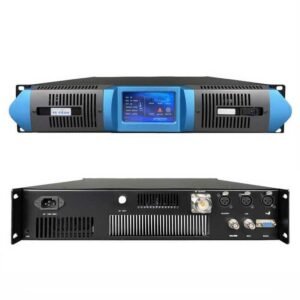
How to Choose the Right Dipole FM Antenna for Your Radio Station
You bought a transmitter but need an antenna to broadcast. Wrong antenna choice wastes transmitter power or covers wrong areas. Dipole antennas are simple and effective but selecting correct specifications matters.
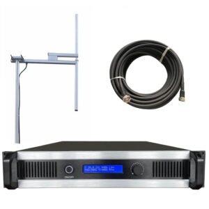
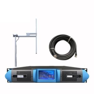
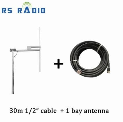
Choose dipole FM antennas by matching power rating to transmitter output, calculating correct length for frequency (468/F in feet), selecting polarization type (vertical/horizontal/circular), checking VSWR below 1.5, and choosing bay configuration (1-4 bays) for desired gain. RS provides complete antenna systems matching our 7W-10KW transmitter range.
I help customers daily at RS select antennas matching their transmitters. Most mistakes come from mismatched power ratings or wrong length calculations.
What Is a Dipole FM Antenna and How Does It Work?
Understanding antenna function helps you choose correctly and troubleshoot problems.
A dipole FM antenna consists of two metal rods extending from a central feed point. Total length equals half wavelength of broadcast frequency. Transmitter sends RF signal through coaxial cable to antenna. Antenna converts electrical energy into electromagnetic waves radiating omnidirectionally covering 360 degrees horizontally.
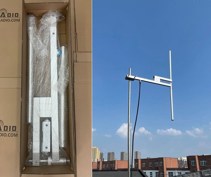
Dipole construction uses two metal tubes or rods mounted vertically or horizontally. Each rod measures quarter wavelength. The two rods connect to coaxial cable center conductor and shield at the feed point. This creates balanced impedance typically 50 ohms matching transmitter output and cable impedance.
Signal flow works simply. Transmitter generates RF power at specific frequency like 100MHz. Power travels through coaxial cable to antenna feed point. Antenna radiates this power as electromagnetic waves. Waves propagate outward at light speed. Receivers within coverage area detect these waves and convert them back to audio.
Wavelength determines physical dimensions. FM broadcast band operates 87.5-108MHz. At 100MHz wavelength equals 3 meters. Half wavelength dipole measures 1.5 meters total length. Each element measures 0.75 meters. Lower frequencies need longer antennas. 88MHz needs 1.7 meters. Higher frequencies need shorter antennas. 108MHz needs 1.39 meters.
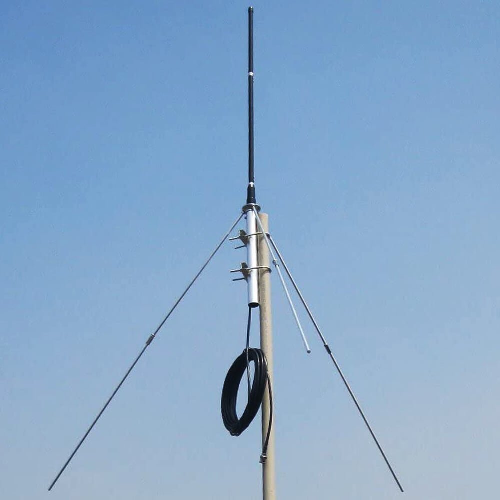
Radiation pattern shows coverage characteristics. Vertical dipoles radiate omnidirectionally in horizontal plane covering 360 degrees equally. Signal strength drops at zenith and nadir above and below antenna. Horizontal dipoles radiate bidirectionally perpendicular to antenna axis. Most FM stations use vertical polarization for vehicle reception.
| Dipole Component | Function | Specification |
|---|---|---|
| Two metal rods | Radiating elements | Quarter wavelength each |
| Feed point | Connect cable | 50 ohm impedance |
| Coaxial cable | Deliver RF power | Low loss type |
Impedance matching ensures efficient power transfer. Transmitter output impedance equals 50 ohms. Coaxial cable impedance equals 50 ohms. Antenna impedance must equal 50 ohms. Mismatched impedance causes reflections wasting power and damaging transmitters. VSWR measures impedance match. VSWR below 1.5 indicates good match. VSWR above 2.0 indicates problems requiring correction.
Current and voltage distribution varies along antenna length. Maximum current occurs at feed point center. Minimum current occurs at rod ends. Maximum voltage occurs at rod ends. Minimum voltage occurs at feed point. This standing wave pattern determines radiation efficiency.
Antenna gain indicates directivity. Simple half-wave dipole provides 0dBd gain radiating equally in all horizontal directions. Stacking multiple dipoles increases gain. Two dipoles stacked vertically provide 3dBd gain. Four dipoles provide 6dBd gain. RS offers 1-bay through 4-bay configurations with gains from 0dBd to 8dBd.
Why Choose a Dipole Antenna for FM Broadcasting?
Many antenna types exist but dipoles dominate FM broadcasting for good reasons.
Choose dipole antennas because they provide omnidirectional coverage, simple construction, reliable operation, easy installation, low cost, good efficiency, and stackable design allowing gain increases. Dipoles work excellently for community stations, religious broadcasting, drive-in theaters, and commercial radio serving circular coverage areas.
Omnidirectional coverage serves most broadcasting needs. Stations serving cities or communities need equal signal strength in all directions. Dipole antennas radiate 360 degrees horizontally covering entire service areas uniformly. Directional antennas concentrate power toward specific directions wasting power in unwanted directions. RS customers operating community stations, churches, and local broadcasters use dipoles covering their entire service areas efficiently.
Simple construction means fewer failure points. Dipole antennas contain only metal rods, feed point connection, and mounting hardware. No complex phasing networks, matching stubs, or moving parts. This simplicity delivers reliability. RS dipole antennas operate continuously for 10-15 years requiring minimal maintenance. Only occasional inspection and cleaning maintains performance.
Easy installation saves time and money. Single bay dipoles weigh 5-8kg. Two people mount them easily in 30-60 minutes. Four bay arrays weigh 25-35kg requiring small crane or hoist. Complete installation including mounting, cable connection, and testing takes 2-4 hours. Compare this to complex directional arrays requiring days of installation and professional riggers.
Low cost fits small station budgets. RS single bay dipole costs $150-250. Two bay costs $350-500. Four bay costs $700-1200. These prices include mounting hardware and weatherproofing. Directional arrays cost $2000-8000 for equivalent power handling. Dipoles deliver best value for stations with limited budgets.
| Dipole Advantage | Benefit | Typical Use |
|---|---|---|
| Omnidirectional | Equal coverage 360° | Community stations |
| Simple design | High reliability | Religious broadcasting |
| Easy installation | Low labor cost | Small commercial stations |
Efficiency converts transmitter power into radiated signal effectively. Well-designed dipoles achieve 85-95% radiation efficiency. Only 5-15% of power dissipates as heat in antenna structure. Compare this to inefficient antennas wasting 30-50% of transmitter power as heat. RS dipoles use large diameter aluminum tubing minimizing resistive losses maximizing radiated power.
Stackable design allows gain increases. Start with single bay dipole providing 0dBd gain. Add second bay later increasing gain to 3dBd doubling coverage area. Add fourth bay reaching 6dBd gain quadrupling coverage area. This scalability lets stations grow coverage without replacing antenna systems. RS offers compatible bay designs allowing easy expansion.
Vertical polarization matches mobile reception. Most car radios use vertical whip antennas. Vertical dipoles match this polarization delivering maximum signal to mobile listeners. Horizontal polarization causes 20-30dB signal loss to vertical receivers. FM broadcasting primarily serves mobile audiences making vertical dipoles ideal.
Weather resistance ensures continuous operation. RS dipoles use marine grade aluminum and stainless steel hardware resisting corrosion. Welded construction prevents water intrusion. UV-resistant paint protects surfaces from sun damage. These antennas withstand wind speeds up to 150 km/h, temperature extremes from -40°C to +60°C, and continuous salt spray in coastal environments.
Wide bandwidth covers entire FM band. Single dipole designed for 100MHz operates efficiently from 88MHz to 108MHz. VSWR remains below 1.5 across this 20MHz bandwidth. This allows frequency changes without antenna replacement. RS dipoles cover complete 87.5-108MHz band accommodating any assigned frequency.
What is the length of dipole antenna for FM radio?
Wrong length causes poor performance and high VSWR damaging transmitters. Calculate precisely for your frequency.
Calculate dipole length using formula: Length (meters) = 142.5 / Frequency (MHz). For 100MHz: 142.5 / 100 = 1.425 meters total length. Each element measures 0.7125 meters. Account for end effect reducing physical length by 5%. Final element length equals 0.677 meters each for 100MHz operation.
Basic formula uses wavelength relationship. Wavelength (meters) = 300 / Frequency (MHz). Half wavelength dipole length = Wavelength / 2 = 150 / Frequency. Simplified formula: Length (meters) = 150 / Frequency (MHz). This provides theoretical length. Example: 100MHz frequency requires 150 / 100 = 1.5 meters theoretical length.
End effect correction accounts for capacitance at rod ends. Electrical length exceeds physical length by approximately 5% due to electric field concentration at ends. Multiply theoretical length by 0.95 velocity factor. Practical formula: Length (meters) = 142.5 / Frequency (MHz). For 100MHz: 142.5 / 100 = 1.425 meters total. Each element measures 0.7125 meters.
| Frequency | Total Length | Each Element |
|---|---|---|
| 88 MHz | 1.62 m | 0.81 m |
| 100 MHz | 1.43 m | 0.71 m |
| 108 MHz | 1.32 m | 0.66 m |
Tube diameter affects length. Larger diameter tubes have more capacitance requiring shorter physical length. RS dipoles use 25mm diameter aluminum tubing. This diameter provides optimal balance between mechanical strength and electrical performance. Very thin tubes (under 10mm) require longer lengths approaching theoretical values. Very thick tubes (over 50mm) require shorter lengths 10-15% below theoretical calculations.
Mounting hardware affects tuning. Mounting brackets add capacitance near feed point. Coaxial connectors add inductance. These effects shift resonant frequency requiring length adjustment. RS dipoles include pre-tuned elements accounting for all mounting hardware. Antennas arrive factory-tuned requiring no field adjustment in most installations.
Frequency selection determines final dimensions. Lower frequencies like 88MHz need longer antennas. 88MHz dipole measures 1.62 meters total or 0.81 meters each element. Middle frequencies like 100MHz measure 1.43 meters total. Higher frequencies like 108MHz need shorter antennas measuring 1.32 meters total or 0.66 meters each element.
Measurement accuracy matters. Measure from element centers not ends. Include all metal in measurement excluding mounting insulators. Use millimeter precision. 10mm length error at 100MHz causes 0.7MHz frequency shift and VSWR increase from 1.2 to 1.8. RS manufactures dipoles with ±5mm tolerance ensuring proper tuning.
Temperature changes affect length. Aluminum expands 23 micrometers per meter per degree Celsius. A 1.4 meter dipole expands 0.6mm for 20°C temperature increase. This shifts frequency only 40kHz having minimal effect on performance. No seasonal adjustment is needed.
Multiple bay stacking maintains individual element lengths. Two bay array uses identical dipoles spaced vertically. Spacing equals one wavelength or slightly more. For 100MHz spacing equals 3 meters minimum. Four bay array uses four identical dipoles spaced 3 meters apart vertically. Total height reaches 9-12 meters. All elements maintain standard half-wave length.
How do I install a dipole antenna for an FM transmitter?
Correct installation ensures maximum performance and safety. Follow proper procedures.
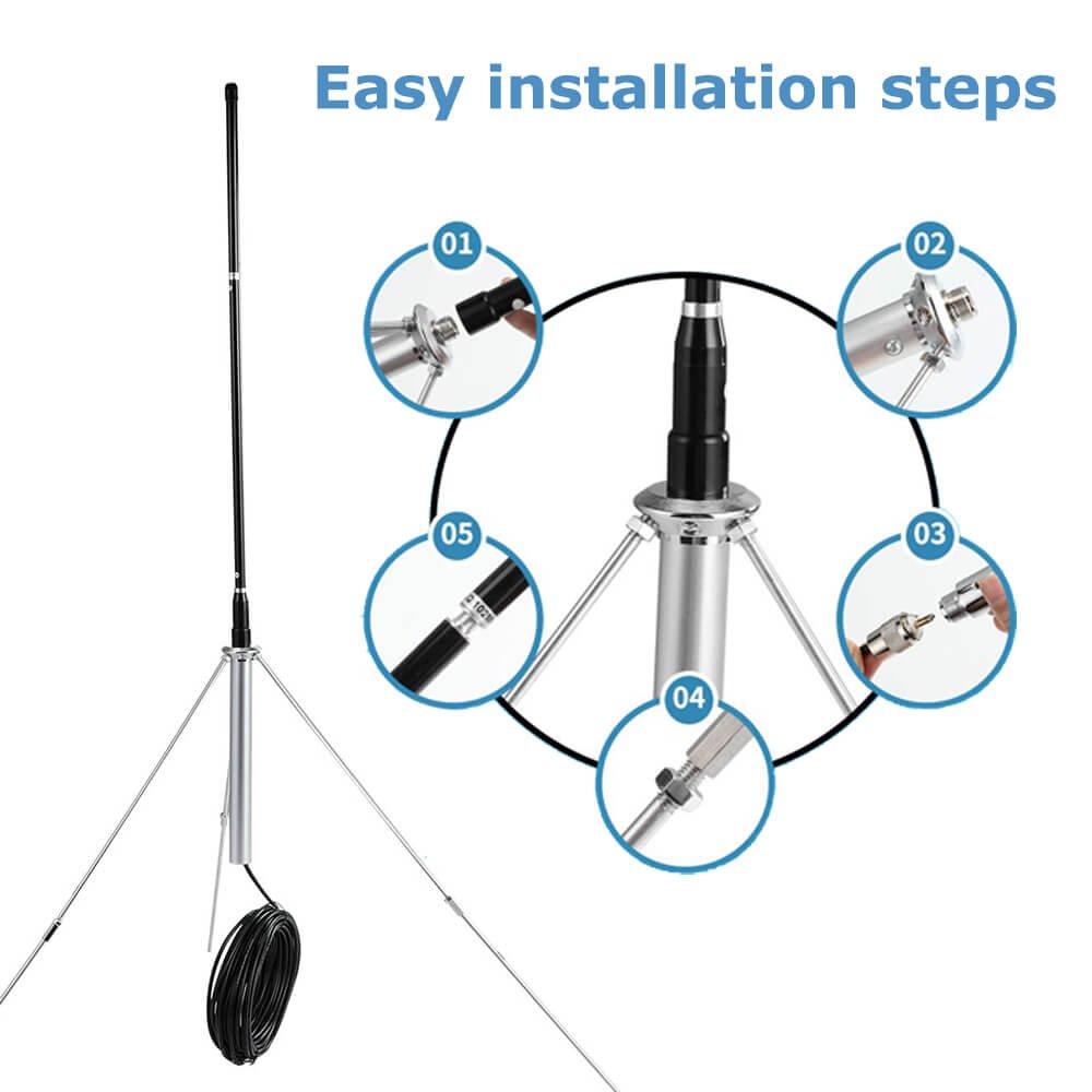
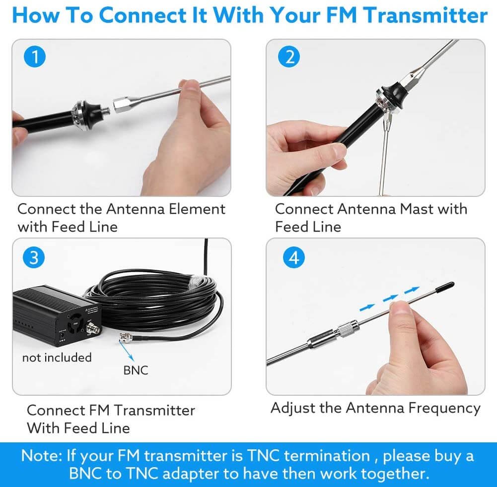
Install dipole antennas by selecting elevated location with clear line of sight, mounting vertical mast or tower, attaching antenna at desired height, connecting coaxial cable using weatherproof connectors, grounding system properly, measuring VSWR below 1.5, and testing broadcast signal. Mount vertically polarized dipoles plumb using level checking vertical alignment.
Site selection affects coverage significantly. Choose highest available location. Roof mounting on tall buildings works excellently. Ground mounting requires tower at least 10 meters high preferably 20-30 meters. Clear line of sight in all directions maximizes omnidirectional coverage. Avoid locations near metal structures, power lines, or other antennas causing interference and detuning.
Tower or mast provides antenna support. Ground mounted installations need tower. Galvanized steel towers handle wind loads safely. Guy wires stabilize towers above 10 meters height. Roof mounting uses vertical mast 2-5 meters high. Secure mast to roof structure with proper brackets. Use weatherproof mounting preventing water leaks. RS provides detailed tower specifications for different antenna configurations.
Antenna mounting requires vertical alignment. Use spirit level checking plumb in two perpendicular directions. Vertical polarization requires precisely vertical elements. Even 10-15 degree tilt reduces signal strength 1-2dB causing coverage asymmetry. Mount antenna to mast using supplied clamps. Tighten bolts to specified torque preventing movement in wind.
Cable connection uses weatherproof techniques. Strip coaxial cable carefully exposing center conductor and shield without damage. Attach connector per manufacturer instructions. RS antennas use standard 7/16" DIN connectors for medium power or N-type for low power. Apply silicone sealant around connection preventing water intrusion. Water in connectors causes corrosion and VSWR problems within months.
Grounding provides lightning protection and safety. Connect antenna mounting bracket to ground rod using 6mm copper wire. Ground rod must penetrate earth at least 2 meters contacting moist soil. Multiple ground rods spaced 3 meters apart work better than single rod. Bond coaxial cable shield to ground at antenna and at transmitter location. RS recommends professional electricians install grounding systems meeting local electrical codes.
Cable routing prevents damage and maintains performance. Secure cable every 1-2 meters using cable clamps preventing wind movement. Avoid sharp bends maintaining minimum 10x cable diameter bend radius. Route away from power cables preventing interference. Use drip loops before entering buildings preventing water infiltration. Properly routed cable lasts 15-20 years. Poor routing causes failures within 2-3 years.
VSWR testing verifies proper installation. Connect VSWR meter between transmitter and cable. Transmit at low power 10-20W. Read forward and reflected power. Calculate VSWR. Values below 1.5 indicate excellent installation. Values 1.5-2.0 acceptable. Values above 2.0 indicate problems requiring correction. Common problems include incorrect antenna length, damaged cable, loose connectors, or nearby metal objects.
Safety precautions prevent accidents. Never work on towers during storms or high winds. Use proper climbing equipment including harness and lanyards. Minimum two people for antenna work with ground spotter. De-energize transmitter before touching antenna or cable. RF burns occur from touching energized antennas. High power transmitters generate lethal voltages at antenna feed points.
Signal testing confirms coverage. Transmit test signal at full power. Drive around service area measuring signal strength using calibrated field strength meter or spectrum analyzer. Signal should measure -60dBm or stronger throughout intended coverage area. Weak areas indicate problems or unrealistic coverage expectations. Adjust antenna height or transmitter power as needed.
Conclusion
Choose dipole FM antennas by calculating length 142.5/Frequency in meters, matching power rating to transmitter output, selecting vertical polarization for mobile coverage, and verifying VSWR below 1.5. Install at maximum available height with proper grounding and weatherproof connections. RS provides complete antenna systems from https://fmradiotx.com/ matching our 7W-10KW transmitter range with 1-4 bay configurations delivering 0-8dBd gain.