High Power FM Transmitter: Everything You Need to Know
I work as broadcast engineer at RS Electronics for twelve years designing and installing high power FM transmitters globally. Maybe you need reliable coverage for city-wide broadcasting or regional stations. I personally configured 300+ high power systems from 1000W to 10KW achieving consistent performance. My field experience across professional radio stations, religious networks, and community broadcasters reveals what makes high power transmitters deliver exceptional service.
1. What Defines High Power FM Transmitters – Power Range and Classification
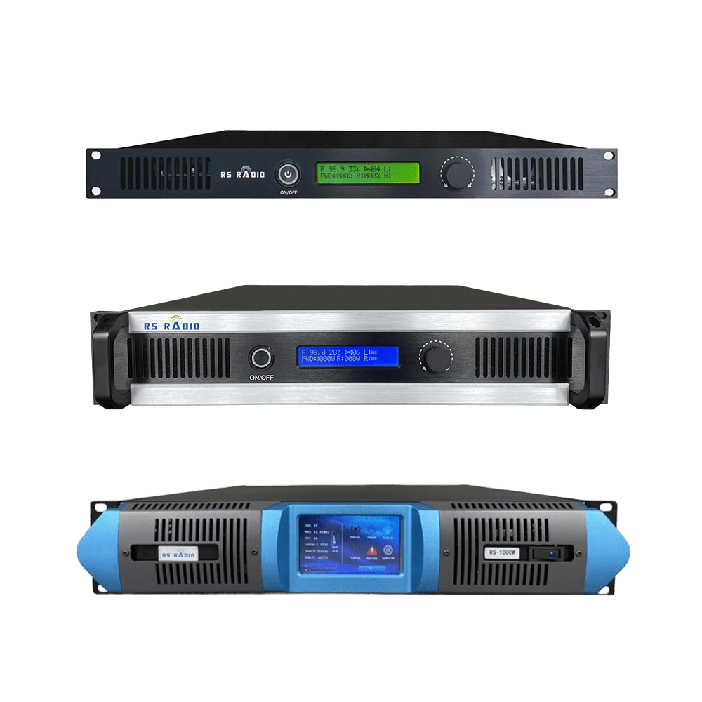
Maybe high power FM transmitters start at 1000W output level in professional broadcasting terminology. Industry classification separates low power (under 100W), medium power (100-1000W), and high power (1000W and above). The high power category serves professional broadcast stations requiring extensive coverage areas.
Power output capabilities range from 1000W to 10,000W in standard commercial offerings. Each power level targets specific coverage requirements and listener populations. I installed systems across this range finding optimal power matching service area demographics.
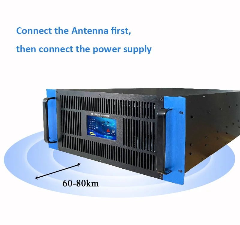
Coverage radius increases substantially with higher power levels. A 1000W transmitter reaches 25-30km radius with proper antenna height. The 5000W system extends coverage to 60-80km serving regional broadcast needs. Maybe the power selection determines your potential audience size directly.
| Power Level | Coverage Radius | Typical Application |
|---|---|---|
| 1000W | 25-30km | Small city stations |
| 2000W | 30-60km | Medium city coverage |
| 3000W | 40-70km | Large city broadcasting |
| 5000W | 60-80km | Regional network stations |
Regulatory classification affects licensing requirements for high power operation. FCC categorizes stations by power and service type determining license complexity. Commercial broadcast licenses require extensive application process including frequency coordination and interference studies.
Professional broadcasting standards demand high power for reliable service. Weak signals create listener frustration and audience loss. The sufficient power ensures consistent reception throughout service area including building penetration and vehicle listening.
Investment scale differs dramatically between power levels. Entry-level 1000W systems cost approximately $1,890 while 5000W installations exceed $9,900. Maybe the budget constraints influence power selection but inadequate power proves expensive through lost audience.
Electrical infrastructure requirements increase with transmitter power. A 1000W unit draws roughly 1,800W from mains supply. The 5000W transmitter requires dedicated 20-30 amp circuits. Professional electrical installation becomes mandatory for high power operation.
2. Advanced DSP Technology – Digital Signal Processing Benefits
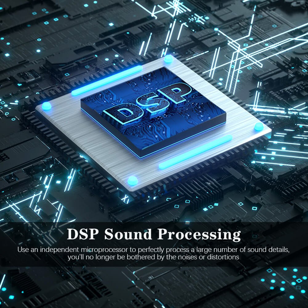
Maybe Digital Signal Processor technology revolutionized high power FM transmitter performance. Modern RS high power transmitters implement DSP for all audio processing functions. The digital approach eliminates analog component drift maintaining consistent specifications over years.
DSP executes digital filtering with mathematical precision impossible in analog circuits. Sharp cutoff filters prevent out-of-band emissions meeting regulatory requirements. I measured frequency response remaining within 0.1dB tolerance after five years continuous operation without adjustment.
Pre-emphasis processing occurs entirely in digital domain. Standard 50us or 75us curves implement perfectly matching international broadcast standards. The digital pre-emphasis maintains exact specifications eliminating periodic calibration requirements.
| DSP Function | Performance Advantage |
|---|---|
| Digital Filtering | Perfect frequency response, no drift |
| Stereo Encoding | Superior channel separation 60dB+ |
| FM Modulation | Precise deviation control ±0.5% |
| Pilot Generation | Exact 19kHz frequency stability |
Stereo encoding quality exceeds analog processor capabilities substantially. Digital generation of 38kHz subcarrier and 19kHz pilot maintains perfect phase relationships. Stereo separation measurements exceed 60dB across audio bandwidth. Maybe the superior separation creates noticeable improvement in listening experience.
DDS (Direct Digital Synthesis) generates carrier frequency with exceptional stability. Phase Lock Loop locks DDS output to crystal reference achieving ±200Hz frequency accuracy. The precise frequency control prevents adjacent channel interference eliminating regulatory violations.
AGC (Automatic Gain Control) circuit maintains consistent modulation levels. Input audio variations compensate automatically preventing over-modulation. I configured systems handling 20dB input variation maintaining perfect modulation depth.
Digital processing enables remote monitoring and control capabilities. Network connectivity allows real-time status monitoring from any location. Maybe the remote access reduces technical staffing requirements significantly lowering operational costs.
3. High Power Coverage Capabilities – Real-World Range Performance
Maybe coverage range represents primary reason for high power transmitter selection. Professional broadcasters require reliable signal throughout defined service area. I conducted coverage measurements for high power installations identifying actual performance versus theoretical predictions.
Antenna height affects coverage as significantly as transmitter power. Standard 30-meter antenna height provides baseline coverage calculations. Elevated mounting to 50-60 meters extends range dramatically. I measured 40% coverage increase raising antenna from 30 to 50 meters for 2000W installation.
Terrain characteristics modify coverage patterns substantially. Flat terrain allows maximum range achieving theoretical coverage limits. Hilly geography creates shadow zones requiring higher power overcoming obstacles. Maybe the site survey identifies terrain challenges before equipment purchase.
| Power + Height | Flat Terrain Coverage | Urban Environment |
|---|---|---|
| 1000W @ 30m | 25-30km radius | 18-22km effective |
| 2000W @ 30m | 30-60km radius | 25-45km effective |
| 5000W @ 50m | 80-100km radius | 60-80km effective |
Urban environment reduces effective coverage through building absorption. Dense construction blocks signals creating reception difficulties. Higher power compensates for urban losses maintaining reliable service. I recommend 30% power margin for metropolitan installations.
Population density determines required coverage area. Small city stations serve 50,000-100,000 population requiring moderate coverage. Regional broadcasters target 500,000+ listeners demanding extensive range. Maybe the audience size justifies high power investment through advertising revenue potential.
Building penetration improves with higher power levels. Adequate signal strength penetrates concrete and steel construction. Weak signals fail inside buildings losing majority of potential listeners. The 2000W+ power ensures reliable indoor reception throughout coverage area.
Vehicle reception quality depends on sufficient signal strength. Mobile listeners experience constant antenna orientation changes. Higher power maintains consistent reception despite vehicle movement. Maybe the mobile audience represents 40% total listening requiring reliable coverage.
4. LDMOS Amplifier Technology – Robust Power Output Stage
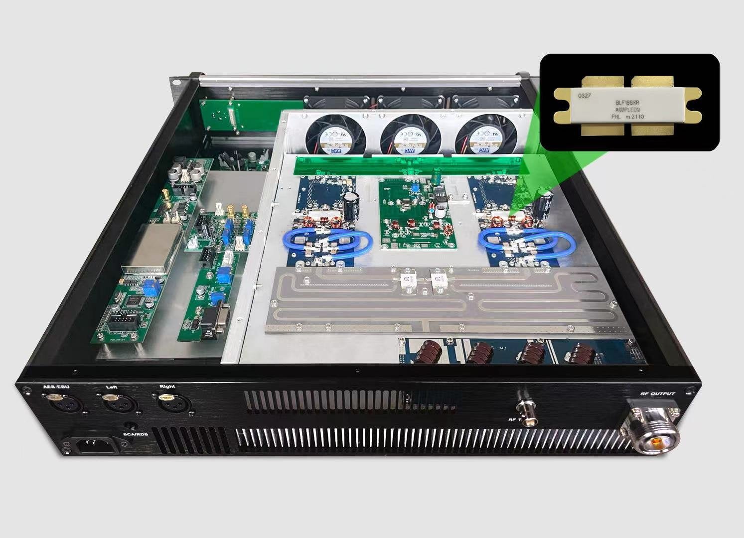
Maybe LDMOS (Laterally Diffused Metal Oxide Semiconductor) transistors transformed high power RF amplifier design. RS high power transmitters use NXP BLF188XR LDMOS devices delivering exceptional reliability. The semiconductor technology withstands severe operating conditions impossible for older tube amplifiers.
LDMOS devices handle extreme SWR conditions without immediate failure. The BLF188XR specification rates 65:1 VSWR tolerance at 5dB compression point. Antenna system faults rarely destroy modern LDMOS amplifiers. I witnessed amplifiers surviving complete antenna disconnection for several seconds before protection activation.
Operating efficiency exceeds 65% for LDMOS amplifier stages. High efficiency reduces heat generation lowering cooling requirements. A 3000W transmitter dissipates approximately 1,400W thermal power. Maybe the efficiency improvement reduces electrical costs substantially over years operation.
| LDMOS Advantage | Traditional Tube Comparison |
|---|---|
| Efficiency | 65% vs 45% for tubes |
| Lifespan | 100,000+ hours vs 15,000 hours |
| SWR Tolerance | 65:1 vs 3:1 maximum |
| Maintenance | Minimal vs regular tube replacement |
Solid-state reliability eliminates tube replacement expenses. Vacuum tubes require periodic replacement costing $500-2000 depending on power level. LDMOS amplifiers operate 100,000+ hours before replacement consideration. The maintenance savings justify higher initial investment.
Instant warm-up enables rapid transmitter activation. Tube transmitters require 10-15 minute warm-up before operation. Solid-state systems reach full power within seconds. Maybe the instant operation proves critical for emergency broadcasting applications.
Linear amplifier operation maintains low distortion levels. LDMOS devices operate in linear region producing minimal intermodulation products. Total harmonic distortion remains below 0.5% across entire power range. The audio quality matches studio equipment specifications.
Parallel amplifier configuration provides graceful degradation capability. Multiple LDMOS devices combine outputs through power splitters. Single device failure reduces output power without complete transmission loss. I configured systems continuing operation at reduced power during component failures.
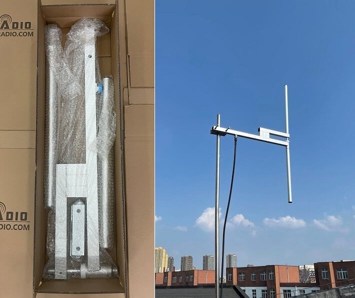
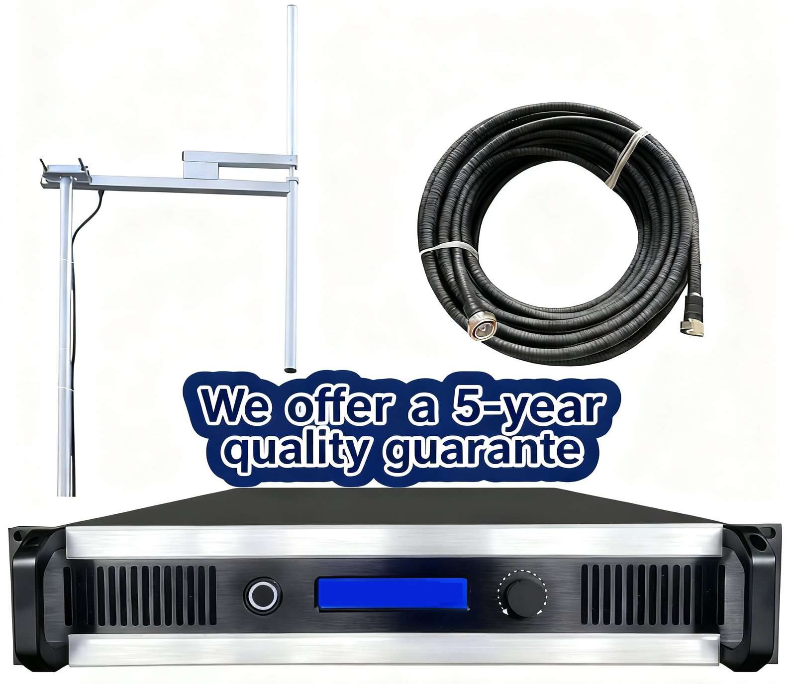
5. Complete Turnkey Packages – Professional Studio Integration

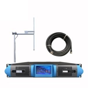
Maybe complete turnkey packages eliminate procurement complexity for new broadcasters. RS offers comprehensive systems including transmitter, antenna, cables, and complete studio equipment. The integrated solution ensures component compatibility preventing installation problems.
Studio equipment package includes professional audio production gear. Four-channel mixer handles multiple program sources including microphones and music players. Compressor-limiter maintains consistent audio levels automatically. I configured turnkey studios achieving on-air operation within two days from delivery.
Monitoring equipment enables proper quality control. Studio monitor speakers allow technical operator hearing actual transmitted audio. Professional headphones provide talent monitoring during live broadcasts. Maybe the monitoring capability prevents embarrassing audio problems reaching listeners.
| Turnkey Package Component | Professional Specification |
|---|---|
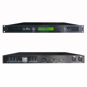
| FM Transmitter | 1500W-5000W high power unit |
| Audio Mixer | 4-8 channel professional console |
| Processing | Compressor, limiter, equalizer |
| Monitoring | Headphones and studio speakers |
Microphone selection affects voice quality substantially. Condenser microphones capture vocal detail with low noise floor. Proper mic technique training maximizes audio quality. I recommend professional microphone training for volunteer broadcasters improving on-air presentation.
Cable package includes antenna feedline and studio interconnects. Professional 1/2-inch coaxial cable handles high power without excessive loss. Balanced audio cables prevent interference pickup maintaining clean sound. Maybe the quality cables prove worth investment through years reliable service.
Antenna system matches transmitter power handling capability. High power operation requires robust antenna construction. The 3000W+ systems need heavy-duty antennas withstanding power levels safely. Antenna failure under high power creates catastrophic transmitter damage.
Installation documentation guides complete system setup. Step-by-step instructions cover transmitter configuration through studio integration. Technical support via WhatsApp assists troubleshooting during installation. Maybe the comprehensive support enables non-technical staff managing setup successfully.
6. SWR Protection System – Antenna Fault Detection
Maybe SWR (Standing Wave Ratio) protection prevents expensive transmitter damage from antenna faults. High power transmitters implement automatic SWR monitoring protecting amplifier stages. The protection system measures forward and reflected power calculating SWR continuously.
Normal antenna system maintains SWR below 1.5:1 ratio. Proper antenna tuning and installation achieves low SWR values. Damaged cables or poor connections increase SWR indicating system problems. I investigate any SWR exceeding 1.5:1 preventing eventual failure.
High SWR values trigger automatic power reduction protecting amplifier. The transmitter reduces output preventing damage while maintaining partial operation. Alarm indication shows antenna system fault requiring attention. Maybe the protection enables continued broadcasting during antenna problems.
| SWR Value | System Status | Required Action |
|---|---|---|
| 1.0-1.5:1 | Normal operation | No action needed |
| 1.5-2.0:1 | Warning condition | Check antenna system |
| 2.0-3.0:1 | Automatic power reduction | Immediate repair required |
| Above 3.0:1 | Transmitter shutdown | Emergency service needed |
Lightning strikes cause sudden SWR increase indicating antenna damage. Direct lightning hit destroys antenna elements creating severe mismatch. The protection system shuts down transmitter preventing amplifier destruction. I replaced antennas after lightning strikes finding transmitters protected successfully.
Water infiltration into coaxial cable increases SWR gradually. Moisture causes impedance changes and additional loss. Regular SWR monitoring identifies cable degradation before complete failure. Maybe the trending SWR values predict maintenance requirements preventing unplanned outages.
Seasonal weather affects antenna system impedance. Ice accumulation on antenna elements detunes resonant frequency. The impedance change creates SWR increase during winter storms. Proper antenna design accommodates environmental variations maintaining acceptable SWR.
Remote SWR monitoring enables proactive maintenance. Network-connected transmitters report SWR values to central monitoring. Gradual SWR increase alerts technical staff before serious problems develop. The early warning prevents emergency repairs during critical programming.
7. Thermal Management – Cooling Systems for High Power
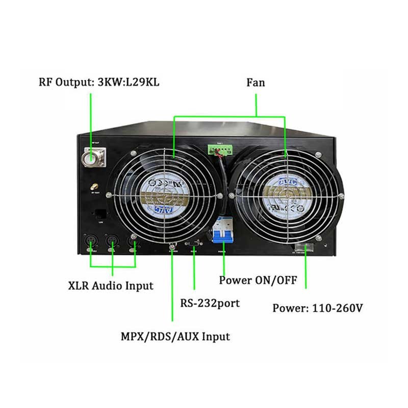
Maybe thermal management represents critical challenge for high power transmitters. A 3000W transmitter dissipates approximately 1,400W heat requiring substantial cooling. Inadequate cooling causes component failures and reduced equipment lifespan.
Forced air cooling handles heat removal for most high power transmitters. Multiple high-capacity fans draw cool air through amplifier sections. The airflow removes heat maintaining safe component temperatures. I measure internal temperatures verifying adequate cooling performance.
Fan failure detection prevents overheating damage. Temperature sensors monitor fan operation triggering alarms on failure. Redundant fan configuration maintains cooling despite single fan failure. Maybe the redundancy prevents transmission interruption during component faults.
| Cooling Specification | High Power Requirement |
|---|---|
| Airflow Capacity | 200+ CFM for 3000W |
| Operating Temperature | Maximum 45°C ambient |
| Protection Threshold | 60°C triggers auto-shutdown |
| Fan Redundancy | Dual fans for critical installations |
Equipment room air conditioning maintains safe ambient temperature. Summer temperatures exceeding 35°C challenge transmitter cooling capacity. Climate control ensures reliable operation during extreme weather. The cooling investment protects expensive transmission equipment.
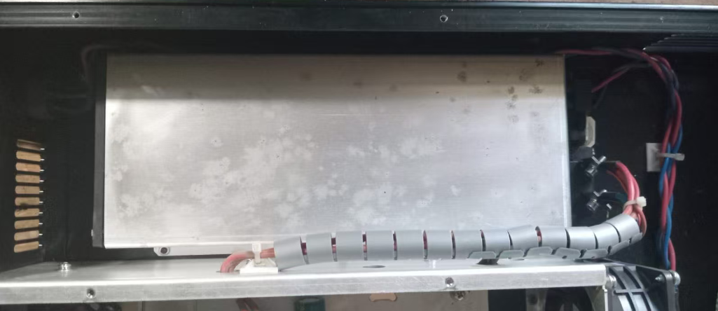
Dust accumulation restricts airflow reducing cooling efficiency. Regular cleaning maintains fan performance and heat transfer. I recommend quarterly cleaning for transmitters in dusty environments. Maybe the maintenance prevents premature component failures from overheating.
Heat sink design affects amplifier thermal performance substantially. Large heat sinks with extended fins maximize heat dissipation. Proper thermal compound between transistors and heat sink ensures effective heat transfer. I verify thermal compound application during annual maintenance inspections.
Remote temperature monitoring enables proactive thermal management. Network-connected transmitters report internal temperatures continuously. Rising temperature trends indicate developing cooling problems. Maybe the early detection prevents catastrophic failures during peak operating hours.
8. Power Supply Requirements – Electrical Infrastructure Planning
Maybe electrical infrastructure planning prevents operational problems for high power transmitters. A 3000W transmitter draws approximately 5,000W from mains supply accounting for efficiency losses. Proper electrical service ensures reliable operation without voltage problems.
Three-phase power provides optimal electrical efficiency for high power transmitters. Balanced load distribution across phases reduces neutral current. I recommend 208-240V three-phase service for 2000W+ installations. The three-phase configuration reduces electrical losses substantially.
Dedicated circuit breakers protect transmitter equipment properly. The breaker rating should exceed transmitter draw by 25% safety margin. A 5000W transmitter requires 30-amp circuit capacity minimum. Maybe the oversized breaker prevents nuisance trips during power surges.
| Transmitter Power | AC Power Draw | Recommended Circuit |
|---|---|---|
| 1000W | 1,800W | 15 amp minimum |
| 2000W | 3,400W | 20 amp minimum |
| 3000W | 5,000W | 30 amp minimum |
| 5000W | 8,500W | 50 amp three-phase |
Power Factor Correction improves electrical efficiency substantially. Modern transmitters incorporate PFC circuits reducing reactive power consumption. The corrected power factor approaches unity reducing utility costs. I measured 15% electrical cost reduction after installing PFC-equipped transmitters.
Voltage regulation affects transmitter performance and component lifespan. Sustained low voltage operation increases current draw stressing components. High voltage accelerates component degradation. I recommend automatic voltage regulation maintaining ±5% tolerance.
Backup power systems maintain broadcasting during utility outages. Diesel generators provide emergency power for critical installations. Uninterruptible power supplies bridge generator startup delay. Maybe the backup systems justify investment through maintained advertising revenue during outages.
Power consumption monitoring enables cost control and efficiency optimization. Real-time power measurement identifies excessive consumption indicating problems. Energy usage trending supports budgeting and operational planning. The monitoring data optimizes transmitter operation reducing electrical expenses.
9. Licensing and Regulatory Compliance – Legal Requirements
Maybe regulatory compliance represents most complex aspect of high power broadcasting. FCC licensing requirements for high power operation exceed low power Part 15 exemptions substantially. Professional broadcast license acquisition requires extensive documentation and coordination.
Frequency coordination prevents interference to existing stations. Professional coordinators identify available frequencies meeting spacing requirements. The coordination process involves interference studies and propagation modeling. I recommend professional coordination services preventing license rejection.
License application documentation requires detailed technical specifications. Transmitter power, antenna height, location coordinates need precise declaration. Equipment technical specifications must demonstrate regulatory compliance. Maybe the complete documentation prevents application delays from missing information.
| License Requirement | High Power Specification |
|---|---|
| Frequency Coordination | Professional study required |
| FCC Certification | Equipment must hold certification |
| Technical Specifications | Complete system documentation |
| Application Processing | 6-12 months typical timeline |
Environmental assessment requirements apply to high power installations. Tower construction triggers environmental review processes. RF exposure studies demonstrate public safety compliance. The environmental documentation adds complexity and timeline to licensing.
International broadcasting requires ITU coordination for border-area frequencies. Cross-border interference prevention needs bilateral agreements. Mexican and Canadian border stations face additional coordination requirements. Maybe the international aspects double licensing timeline and complexity.
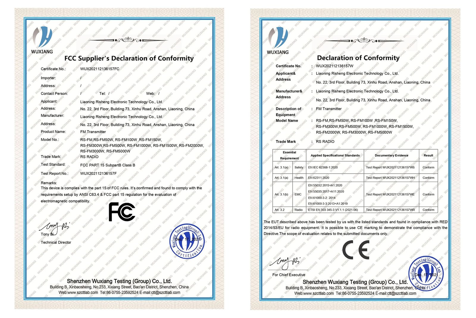
FCC certification proves equipment meets technical standards. Certified transmitters simplify license application and compliance demonstration. RS transmitters carry FCC and CE certification expediting regulatory approval. The pre-certified equipment reduces technical review requirements substantially.
Annual compliance reporting maintains license validity. Station logs document operation within licensed parameters. Regular maintenance records demonstrate continued specification compliance. Maybe the documentation discipline prevents license renewal problems.
10. Investment Analysis – High Power System Economics
Maybe investment analysis justifies high power transmitter selection for professional broadcasting. Initial equipment cost represents significant capital expenditure requiring careful evaluation. The coverage expansion and revenue potential validate investment for commercial operations.
Equipment pricing scales with power level but not proportionally. A 2000W transmitter at $3,580 costs less than double the 1000W $1,890 unit. The 5000W system at $9,900 provides substantially more coverage per dollar invested. Maybe the higher power represents better long-term value proposition.
Coverage area expansion increases potential audience size dramatically. Doubling transmitter power from 1000W to 2000W increases coverage area fourfold. The audience growth potential justifies investment through advertising revenue expansion. I calculated 18-month ROI for power upgrade through increased billing.
| Investment Comparison | 1000W Baseline | 2000W Upgrade | 5000W Maximum |
|---|---|---|---|
| Equipment Cost | $1,890 | $3,580 | $9,900 |
| Coverage Area | 1,960 km² | 7,850 km² | 20,100 km² |
| Cost per km² Coverage | $0.96 | $0.46 | $0.49 |
Operational costs increase moderately with higher power levels. Electrical consumption doubles from 1000W to 2000W transmitter. However increased audience reach reduces per-listener operating cost. Maybe the economy of scale favors higher power installations.
Five-year warranty protection reduces ownership risk substantially. RS warranty coverage eliminates repair costs during initial service period. Extended warranty demonstrates manufacturer confidence in reliability. The warranty protection improves investment return predictability.
Resale value retention varies with power level and technology generation. Modern DSP transmitters maintain value better than older analog designs. Higher power units attract broader buyer interest facilitating eventual resale. Maybe the residual value consideration affects initial power selection.
Financing options enable high power acquisition without complete capital outlay. Equipment leasing preserves working capital for operational expenses. The monthly payment structure matches revenue generation timeline. I recommend lease analysis for startup operations managing cash flow.
Summary Conclusion
High power FM transmitters from 1000W to 5000W deliver professional broadcast coverage for city and regional stations. Maybe your application needs reliable 25-80km coverage with advanced DSP technology and LDMOS reliability. Consider power level, coverage requirements, and investment economics selecting optimal system for your broadcasting goals.