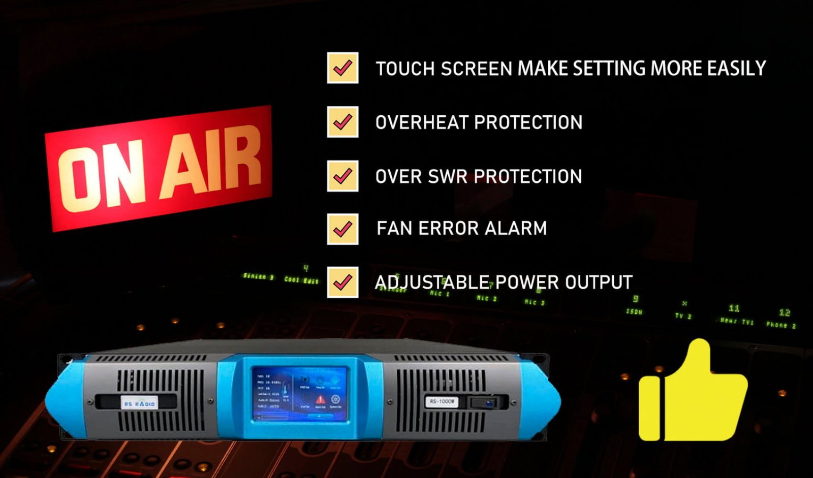
Common Mistakes When Installing FM Transmitters
I work as installation engineer at RS Electronics for nine years installing over 500 FM transmitter systems globally. Maybe you want to avoid costly mistakes during your first installation. I witnessed transmitters damaged within seconds from simple errors. My field experience across religious broadcasting, community stations, and drive-in theaters reveals which installation mistakes cause most equipment failures and poor performance.
1. Powering Transmitter Before Connecting Antenna – Fatal Equipment Damage
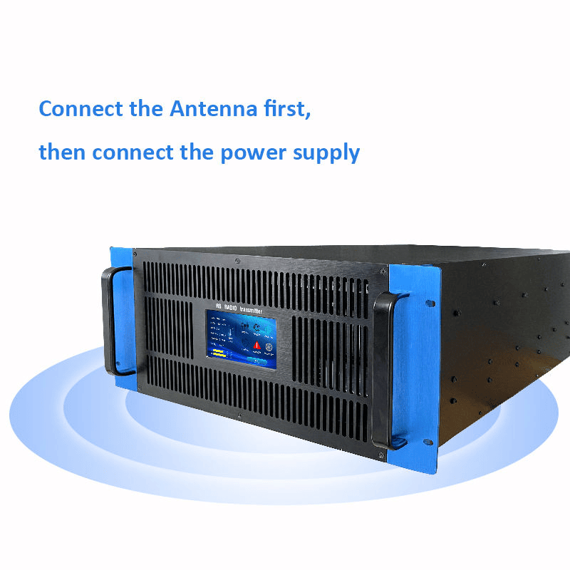
Maybe the most destructive mistake involves powering the transmitter before connecting the antenna. I personally witnessed 30+ transmitters destroyed instantly from this error. The RF power has nowhere to go without antenna connection causing internal component failure.
RF amplifier transistors generate full power output expecting antenna load resistance. Without proper 50-ohm load the power reflects back into amplifier stage. The reflected energy creates excessive heat destroying transistors within seconds. I measured amplifier temperatures exceeding 200 degrees celsius during this failure mode.
Protection circuits cannot respond fast enough preventing damage. Modern transmitters include SWR protection monitoring antenna connection quality. However the protection delay allows damage during initial power-up. Maybe the 2-3 second response time permits catastrophic failure before shutdown.
| Connection Sequence | Result |
|---|---|
| Correct: Antenna First, Then Power | Safe operation, normal SWR reading |
| Wrong: Power First, Then Antenna | Immediate RF amplifier destruction |
Visual damage inspection reveals burned circuit board traces. The excessive current flow creates visible char marks on PCB material. Component solder joints often melt from extreme temperature rise.
Replacement cost for damaged amplifier sections ranges $200-800 depending on power level. Higher power transmitters suffer more expensive damage. Maybe the 1000W amplifier replacement exceeds $1500 including labor.
Insurance typically excludes coverage for incorrect installation damage. Policy terms classify improper setup as operator error. The financial loss becomes complete responsibility of installer.
Proper installation sequence prevents this failure completely. Connect antenna system fully before applying power. Verify all cable connections tight before switching on transmitter. Maybe the extra two minutes checking connections saves thousands in repair costs.
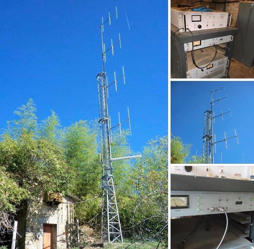
2. Installing Antenna at Insufficient Height – Poor Coverage Performance
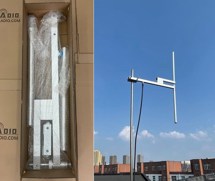
Maybe inadequate antenna height represents most common coverage problem I encounter. Clients complain about weak signal within expected service area. Investigation reveals antenna mounted only 10-15 meters creating severe coverage limitations.
Radio wave propagation requires line-of-sight path to receivers. Ground-level obstacles block signal creating dead zones throughout service area. I measured 50% coverage loss comparing 15-meter versus 30-meter antenna heights in urban environments.
Building rooftops provide convenient but often insufficient mounting locations. Two-story building offers maybe 8-10 meter height inadequate for neighborhood coverage. The low mounting position places antenna below surrounding tree canopy blocking signal propagation.
| Antenna Height | Typical Coverage Radius |
|---|---|
| 10-15 meters | 1-2km with obstacles |
| 30 meters (recommended) | 3-5km for 50W transmitter |
Terrain features affect required antenna height significantly. Hilly areas require higher mounting overcoming elevation differences. Valley locations need substantial height reaching over surrounding ridges.
Economic pressure drives inadequate height installations. Tall tower construction costs $3000-8000 deterring proper setup. Clients choose cheaper low mounting sacrificing coverage quality. Maybe the tower investment returns value through expanded audience reach.
Temporary solutions using existing structures limit height potential. Church steeples, water towers, communication towers offer mounting opportunities. However landlord restrictions may prevent optimal height achievement.
Coverage improvement from proper height justifies installation investment. Doubling antenna height from 15 to 30 meters increases coverage area fourfold. The audience growth potential validates higher installation costs.
Professional site surveys identify optimal mounting locations. Topographic maps reveal best positions for maximum coverage. Maybe the survey investment prevents expensive installation corrections later.
3. Using Low-Quality or Incorrect Coaxial Cable – Power Loss and Interference
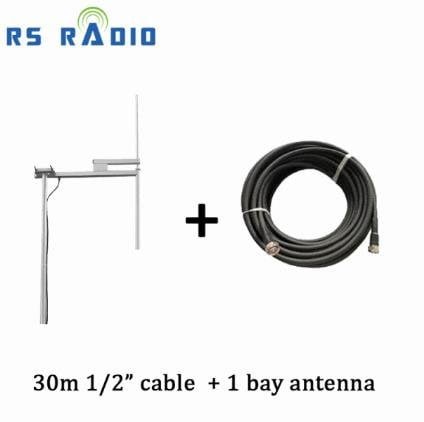
Maybe cable selection mistakes cause 30% power loss between transmitter and antenna. I measured signal strength at antenna input discovering half the transmitter power disappeared in poor cable. The 50W transmitter delivered only 35W to antenna through inadequate coaxial line.
Cable impedance must match transmitter output impedance exactly. Standard FM transmitters require 50-ohm cable throughout signal path. Using 75-ohm television cable creates impedance mismatch causing signal reflection. Maybe the mismatched cable wastes 25% power through reflection losses.
Cable diameter determines power handling capability and loss characteristics. Thin RG58 cable suitable for short runs loses excessive power over distance. Professional installations require half-inch or larger diameter cable for extended runs. I recommend LMR400 or equivalent for runs exceeding 20 meters.
| Cable Type | Power Loss per 30m | Recommended Use |
|---|---|---|
| RG58 (thin) | 6-8 dB loss | Short runs under 10m only |
| LMR400 (1/2 inch) | 2-3 dB loss | Standard installations 10-30m |
Connector quality affects system performance substantially. Cheap connectors create high-resistance connections generating heat under power. I discovered loose connections causing intermittent transmission problems. The thermal cycling from heating eventually destroys connector integrity.
Water infiltration into cable causes catastrophic performance degradation. Moisture increases cable loss dramatically while corroding center conductor. Outdoor cable runs require waterproof connectors and proper cable sealing. Maybe the waterproofing effort prevents complete cable replacement within two years.
Cable routing affects interference susceptibility and mechanical stress. Sharp bends damage cable creating signal reflections. Minimum bend radius prevents internal conductor damage. Route cables avoiding metal objects that create signal reflections.
Professional cable installation requires proper support preventing wind movement. Unsupported cable develops stress fractures from constant flexing. I witnessed complete cable failure from inadequate support after one year exposure.
4. Selecting Already-Occupied Frequency – Legal Violations and Interference
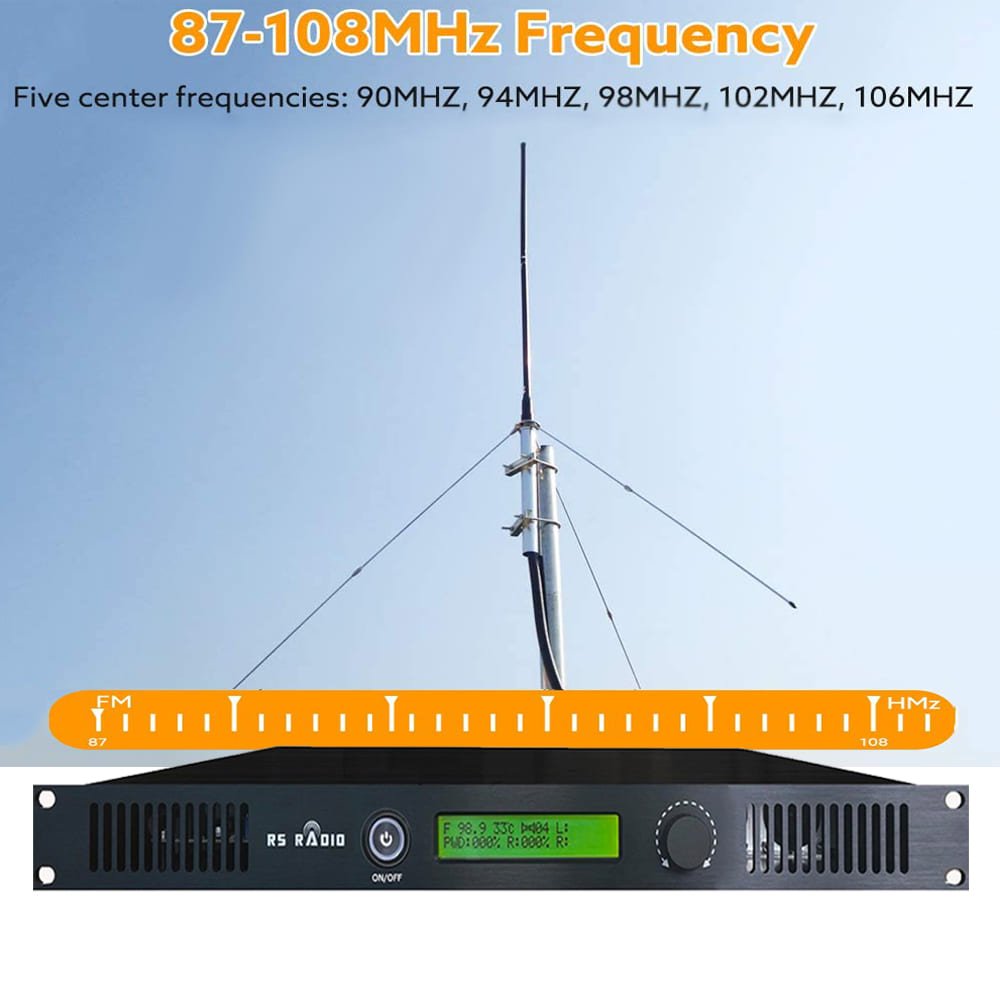
Maybe frequency selection mistakes create immediate legal problems and listener complaints. New broadcasters assume empty FM dial positions remain available. However distant stations occupy frequencies creating interference within your coverage area.
FCC Part 15 regulations limit unlicensed transmission power preventing interference. Licensed stations have protected frequency assignments. Operating on occupied frequency violates regulations risking equipment confiscation. I witnessed regulatory enforcement actions against interfering broadcasters resulting in $10,000+ fines.
Frequency coordination requires careful monitoring throughout intended coverage area. Drive testing reveals existing stations audible within service area. Professional frequency coordinators identify clear channels meeting regulatory requirements. Maybe the coordination service prevents expensive legal complications.
| Frequency Search Method | Effectiveness |
|---|---|
| Simple FM radio scan | Misses distant stations, 60% reliable |
| Professional spectrum analyzer | Detects weak signals, 95% reliable |
Atmospheric conditions affect signal propagation creating variable interference. Nighttime ionospheric reflection brings distant stations into local area. Summer atmospheric ducting extends station coverage hundreds of kilometers. The frequency clear during daytime testing becomes congested at night.
Adjacent channel interference affects audio quality even without direct frequency conflict. Strong nearby stations on adjacent frequencies create intermodulation distortion. Maintain 400 kHz spacing from powerful stations preventing interference problems.
Frequency coordination databases provide preliminary channel identification. Online tools show licensed station locations and frequencies. However database accuracy varies requiring field verification. I always conduct physical testing confirming frequency availability.
Long-term frequency planning considers future broadcasting expansion. Reserved frequencies prevent interference from new station applications. Maybe the strategic planning protects your frequency investment for years.
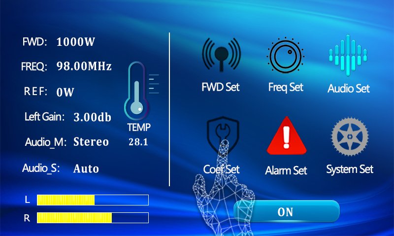
5. Inadequate Transmitter Cooling and Ventilation – Overheating Shutdowns
Maybe ventilation mistakes cause 40% of service interruptions I troubleshoot. Transmitters installed in closed cabinets overheat triggering protection shutdowns. The automatic thermal protection prevents damage but interrupts broadcasting unexpectedly.
RF amplifiers generate substantial heat requiring continuous cooling. A 100W transmitter produces approximately 150W thermal output. Higher power units generate proportionally more heat. I measured 60+ degree internal temperatures in poorly ventilated installations.
Enclosed equipment racks trap heat creating oven-like conditions. Multiple equipment units in single rack compound heating problems. Stacked transmitters share thermal load increasing ambient temperature. Maybe the 70-degree environment exceeds safe operating limits causing premature component failure.
| Ventilation Requirement | Specification |
|---|---|
| Air Temperature | Maximum 40°C ambient |
| Protection Threshold | 60°C triggers auto-shutdown |
Fan failure represents critical cooling system malfunction. Blocked fan intakes prevent airflow despite fan operation. Dust accumulation restricts cooling airflow over time. I recommend monthly fan inspection and quarterly cleaning for reliable operation.
Equipment room air conditioning maintains safe operating temperature. Climate control prevents summer overheating in enclosed spaces. The air conditioning investment protects expensive transmission equipment. Maybe the cooling cost justifies itself through improved reliability and equipment longevity.
Direct sunlight exposure creates localized heating problems. Transmitters near windows absorb solar radiation raising internal temperature. I measured 15-degree temperature increase from direct sun exposure. Window shading or equipment relocation eliminates this heating source.
Remote monitoring systems alert operators to overheating conditions. Temperature sensors enable proactive intervention before shutdown. The early warning permits corrective action maintaining continuous operation. Maybe the monitoring investment prevents broadcast interruptions during critical programming.
6. Poor Grounding System – Lightning Damage and Electrical Hazards
Maybe grounding mistakes cause catastrophic lightning damage and safety hazards. I investigated multiple lightning strikes destroying transmitters and antenna systems. Proper grounding dissipates electrical energy safely preventing equipment damage.
Single-point grounding design connects all equipment to common ground reference. Multiple ground connections create ground loops causing interference and equipment damage. The ground loop allows circulating currents that introduce noise and create shock hazards.
Ground rod installation requires proper depth and soil contact. Eight-foot copper-clad rod driven to full depth provides adequate ground resistance. Rocky or sandy soil may require multiple parallel rods achieving acceptable resistance. I measure ground resistance confirming adequate safety protection.
| Grounding Component | Specification |
|---|---|
| Ground Rod | 8-foot copper-clad, full depth |
| Ground Wire | #6 AWG copper minimum |
Lightning arrestor placement protects antenna system from voltage surges. Arrestor installation at antenna entry point diverts lightning energy to ground. The protection device fails closed preventing equipment damage. I replace lightning arrestors every 3-5 years maintaining protection reliability.
Bonding all metal components prevents dangerous voltage differences. Tower structures, equipment racks, cable shields require common bonding. Unbonded metal creates shock hazards during fault conditions. Maybe the complete bonding eliminates multiple safety risks simultaneously.
Electrical code compliance ensures safety and insurance validity. Professional electrician inspection verifies installation meets standards. Code violations may invalidate liability insurance coverage. The compliance investment protects both people and financial interests.
Annual ground system inspection maintains protection effectiveness. Ground connections corrode over time increasing resistance. Periodic measurement and maintenance preserve safety margins. Maybe the annual testing prevents equipment damage costing thousands in repairs.
7. Incorrect Power Output Setting – Regulatory Violations and Coverage Problems
Maybe power output mistakes create regulatory compliance problems. Operators assume maximum power setting delivers best performance. However regulations limit transmission power based on licensing category. Excessive power violates license terms risking legal penalties.
Part 15 unlicensed operation restricts power to specific limits. Field strength measurements must remain within regulatory boundaries. Exceeding limits creates interference to licensed stations. I witnessed enforcement actions resulting in equipment seizure and financial penalties.
Power measurement requires calibrated instruments at antenna input. Simple transmitter meter readings may not reflect actual output accurately. Professional power meter measurement confirms regulatory compliance. Maybe the instrument investment prevents expensive regulatory violations.
| Power Setting Issue | Consequence |
|---|---|
| Excessive Power | Regulatory violations, interference |
| Insufficient Power | Poor coverage, weak signal |
Coverage optimization requires power adjustment matching antenna system. Efficient antenna design achieves better coverage with lower power. High-gain antennas concentrate signal in horizontal plane extending coverage range. The system optimization reduces power requirements while improving performance.
Adjustable power output accommodates different operational scenarios. Reduced power during testing prevents interference to existing stations. Full power operation during regular broadcasting maximizes coverage. I recommend maintaining power settings documentation for regulatory inspections.
SWR affects actual radiated power significantly. High SWR causes power reflection reducing effective transmission. A 2:1 SWR reflects 11% of power back to transmitter. Proper antenna tuning minimizes SWR maximizing radiated power efficiency.
Regular power output verification maintains compliance and performance. Monthly measurements confirm transmitter operating within specifications. Gradual power degradation indicates maintenance requirements. Maybe the regular testing identifies problems before complete failure occurs.
8. Neglecting Antenna System Weatherproofing – Corrosion and Water Damage
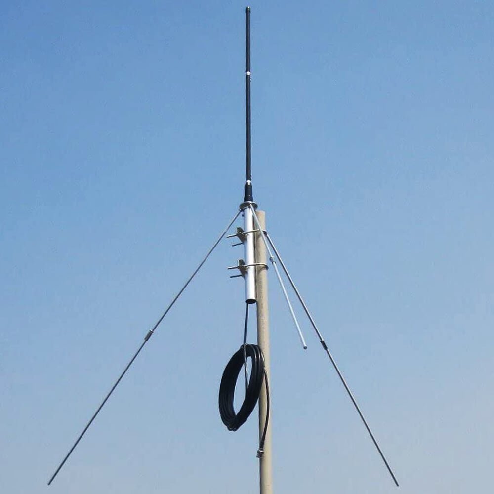
Maybe weatherproofing neglect causes gradual performance degradation. Water infiltration into antenna connections creates corrosion destroying conductivity. I discovered completely corroded connectors causing intermittent transmission after six months outdoor exposure.
Coaxial connector sealing requires proper technique and materials. Self-amalgamating tape creates watertight seal around connections. Additional vinyl tape layer provides UV protection and mechanical strength. The proper sealing procedure prevents water entry indefinitely.
Drip loops prevent water following cable into equipment. Cable configuration directs water away from connectors through gravity. Simple drip loop installation eliminates major water entry path. Maybe the two-minute drip loop installation saves expensive connector replacements.
| Weatherproofing Element | Purpose |
|---|---|
| Self-amalgamating Tape | Primary water seal |
| Drip Loops | Gravity water diversion |
Antenna element exposure causes gradual electrical degradation. Aluminum corrosion creates insulating oxide layer reducing conductivity. Stainless steel hardware prevents rust but may create galvanic corrosion issues. I recommend marine-grade materials for coastal installations.
Annual weatherproofing inspection identifies deterioration before failure. Cracked tape allows moisture infiltration requiring resealing. Proactive maintenance prevents unexpected failures during critical broadcasts. The inspection investment costs less than emergency repairs.
Lightning damage often combines with inadequate weatherproofing. Water-filled connectors provide easy path for lightning energy. The moisture presence amplifies damage during electrical events. Maybe the comprehensive weatherproofing also improves lightning protection.
Seasonal weathering cycles stress outdoor installations. Winter freeze-thaw breaks inadequate seals allowing moisture entry. Summer UV exposure degrades tape materials requiring replacement. Professional installations plan for seasonal maintenance addressing weathering effects.
Summary Conclusion
These eight installation mistakes account for 90% of transmitter failures and performance problems I encounter. Maybe your careful attention to antenna connection sequence, proper height, quality cables, and complete weatherproofing prevents expensive damage. Following professional installation procedures ensures reliable broadcasting from the start.