7 Early Warning Signs Your FM Transmitter Needs Service
Catch Small Problems Before They Become Expensive Failures
Last month I got an emergency call from a church broadcaster in Kenya. Their Sunday morning service went silent mid-broadcast—transmitter completely dead. When I diagnosed the issue remotely, I found a failed power amplifier that had been showing warning signs for weeks. The burnt smell, rising temperature readings, and gradual power decline were all ignored. A preventive service call became a $580 amplifier replacement plus lost broadcast time during Easter weekend.
This happens more often than it should. FM transmitters are reliable machines, but they give early warnings before major failures. Maybe you’ve noticed your coverage shrinking, or listeners complain about audio quality, or your equipment runs hotter than usual. These aren’t random issues—they’re your transmitter asking for help.
I’m an RF engineer at RS, and I’ve diagnosed over 400 transmitter failures in the past 8 years. Most could have been prevented with early intervention. This guide shows you the 7 warning signs that mean your transmitter needs professional service, what causes each problem, and when you can handle it yourself versus when you need expert help.
Why Early Detection Matters
Before diving into specific warning signs, understand why catching problems early saves you money and headaches:
Cost Escalation: A $50 capacitor replacement caught early prevents $500+ power amplifier damage later. Component failures cascade—one failed part stresses others until multiple systems fail.
Broadcast Continuity: Minor issues you can fix during scheduled maintenance. Major failures happen at worst times (holidays, special events, overnight) requiring emergency service calls at premium rates.
Regulatory Compliance: Degraded transmitters drift off-frequency, exceed modulation limits, or cause interference. This risks FCC fines (USA), license suspension, or legal liability.
Equipment Lifespan: Well-maintained transmitters last 10-15 years. Neglected ones fail in 3-5 years. The difference is catching and addressing early warning signs.
Now let’s examine the 7 critical warning signs in detail.
Early Warning Sign #1: Coverage Area Noticeably Shrinking

What You’ll Notice
Listeners report signal dropout in areas that previously had reliable reception. Maybe your campus radio reached the south parking lot but now cuts out halfway there. Or church members driving home say the signal fades 2 km earlier than it used to. Coverage degradation happens gradually—you might not notice until listeners complain.
Technical Causes
Reduced Output Power: Internal component degradation (aging transistors, dried capacitors) reduces actual output even though meter shows normal readings. A transmitter rated 100W might only deliver 60W after component aging.
Antenna System Deterioration:
- Coaxial cable oxidation increases loss (cable rated 1.2 dB loss when new becomes 3.5 dB after 5 years)
- Antenna element corrosion changes impedance
- Water intrusion in connectors creates high SWR
- Lightning damage to antenna (even near-miss strikes)
Increased Reflected Power: Poor antenna match reflects power back to transmitter. This reduces radiated power and stresses amplifier components, creating a downward spiral.
What You Can Check Yourself
-
Compare power meter readings: Note current forward/reflected power readings. Compare to installation records or manufacturer specs. Forward power 10%+ below rated is concerning. Reflected power >5% of forward power indicates antenna issues.
-
Visual inspection: Check coaxial connectors for corrosion (green oxidation), water damage, or looseness. Inspect antenna for physical damage, bent elements, or rust.
-
Reception test: Drive the coverage area perimeter with calibrated receiver, comparing current reception to previous surveys.
When You Need Professional Service
- Forward power declined >15% from rated output
- Reflected power >10% of forward power (SWR >1.5:1)
- Coverage loss continues despite visual inspection showing no obvious damage
- You lack proper RF test equipment (power meter, antenna analyzer, spectrum analyzer)
Risk if Ignored: Gradual coverage loss continues until you’re serving 30-50% of original area. Listeners abandon your station permanently. Component stress accelerates, leading to catastrophic failure.
Early Warning Sign #2: Audio Quality Deterioration
What You’ll Notice
Your broadcast audio sounds worse than studio audio. Maybe distortion appears during loud passages, or constant background hiss increases, or stereo separation weakens. Listeners describe your station as "muddy," "harsh," or "noisy" compared to competitors.
Technical Causes
Audio Input Stage Problems:
- Degraded input coupling capacitors distort low frequencies
- Failed audio transformers reduce dynamic range
- Contaminated input connectors create intermittent noise
Modulation Circuit Issues:
- Drift in modulation level causes under-modulation (weak sound) or over-modulation (distortion)
- Aging varactor diodes in FM modulator reduce linearity
- Pre-emphasis circuit component tolerance shifts change frequency response
Power Supply Noise:
- Failing filter capacitors allow AC ripple into audio path (causes 50/60 Hz hum)
- Insufficient voltage regulation creates noise during high modulation
- Poor grounding introduces noise from other equipment
Stereo Encoder Problems:
- 19 kHz pilot tone level incorrect (reduces stereo separation)
- L-R channel phase shift (stereo image becomes narrow)
- Encoder component aging increases distortion
What You Can Check Yourself
-
Compare audio paths: Play same source through transmitter and directly to speakers. If broadcast version sounds worse, problem is in transmitter. If both sound bad, problem is upstream (mixer, processor).
-
Check audio levels: Input and output audio level meters on transmitter should show consistent, appropriate levels. Levels too low or constantly peaking indicate problems.
-
Test connections: Verify all audio connections secure. Clean connector contacts with contact cleaner. Try different input (if transmitter has multiple inputs) to isolate problem.
-
Listen for specific patterns:
- Constant hum = power supply or ground loop
- Distortion on peaks only = modulation too high or limiter failing
- High-frequency harshness = pre-emphasis circuit drift
- Stereo sounds mono = stereo encoder failure
When You Need Professional Service
- Audio quality problems persist after checking all connections and input sources
- You hear distortion that doesn’t appear in studio monitoring
- Stereo separation (check with receiver in stereo mode) sounds narrow or absent
- Background noise noticeably increased compared to when transmitter was new
- You lack audio test equipment (oscilloscope, audio analyzer, modulation monitor)
Technical Service Required:
- Modulation depth calibration (requires modulation monitor)
- Audio stage component replacement (capacitors, transistors)
- Stereo encoder alignment (needs specialized test gear)
- Power supply filter capacitor replacement
Risk if Ignored: Listeners perceive your station as low-quality and tune to competitors. Over-modulation risks regulatory violations. Audio stage failure can damage transmitter’s RF section.
Early Warning Sign #3: Excessive Heat or Abnormal Cooling Fan Behavior
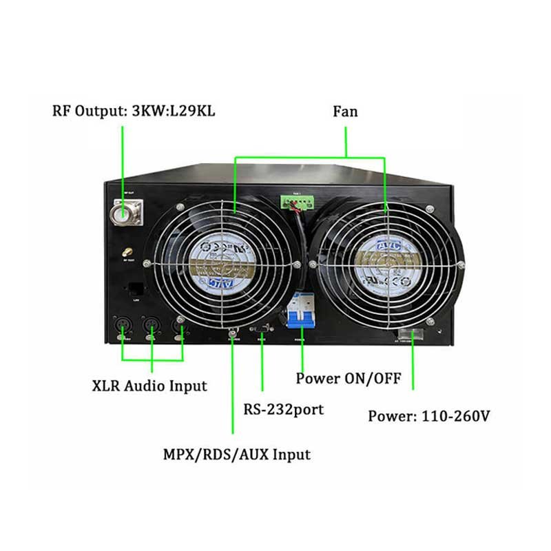
What You’ll Notice
The transmitter cabinet feels hotter than usual when you touch it. Or cooling fans run constantly at high speed, or make grinding/rattling noises, or cycle on/off rapidly. Maybe the LCD display shows higher internal temperature readings than normal. In extreme cases, transmitter shuts down with over-temperature protection.
Technical Causes
Cooling System Degradation:
- Dust accumulation blocks airflow through heat sinks
- Fan bearings wear out causing reduced RPM or failure
- Thermal grease between power transistors and heat sink dries out
- Blocked air intake/exhaust vents
Increased Power Dissipation:
- Component aging increases internal resistance (more heat generated)
- High SWR from antenna problems reflects power back as heat
- Voltage regulation issues cause excess heat in power supply
- Failed thermal protection sensors don’t trigger cooling properly
Environmental Factors:
- Ambient temperature increased (summer, poor room ventilation)
- Direct sunlight on equipment
- Other heat-generating equipment too close
- Rack ventilation inadequate for power level
What You Can Check Yourself
-
Visual inspection and cleaning:
- Power off transmitter and disconnect from AC
- Remove cover (if manufacturer allows user access)
- Use compressed air to blow out dust from heat sinks, fans, circuit boards
- Check fan rotation freely by hand
- Verify air intake/exhaust not blocked
-
Temperature monitoring:
- Record normal operating temperature from transmitter display
- Check after cleaning—temperature should drop 5-10°C if dust was problem
- Verify room ambient temperature hasn’t changed
-
Fan testing:
- Listen for bearing noise (grinding, squealing)
- Observe fan speed—should be steady at operating temperature
- Check for vibration (indicates bearing wear)
-
Antenna system check:
- High reflected power causes heat. Check SWR (see Warning Sign #1)
When You Need Professional Service
- Internal temperature >60°C (140°F) even after cleaning
- Fans physically failed or making loud bearing noise
- Over-temperature shutdowns occur regularly
- Heat concentrated in one section (indicates specific component failure)
- Cabinet or heat sink too hot to touch comfortably
- Temperature readings don’t match actual heat (sensor failure)
Professional Maintenance Needed:
- Fan replacement (requires matching specifications)
- Thermal compound reapplication on power transistors
- Component-level diagnosis of heat source
- Airflow pattern analysis and modification
- Replacement of failing power transistors or amplifier modules
Risk if Ignored: Heat is the #1 killer of electronic components. Every 10°C temperature increase cuts component lifespan in half. Operating at 70°C versus design maximum 50°C reduces expected life from 10 years to 2.5 years. Eventually causes catastrophic failure requiring expensive repairs or replacement.
Early Warning Sign #4: Fluctuating Power Output or SWR Readings
What You’ll Notice
The transmitter’s forward power, reflected power, or SWR meters show unstable readings that bounce around instead of steady values. Or readings gradually drift over hours of operation. Or values that were normal last month are now consistently different. This is one of the most important diagnostic indicators—stable readings mean healthy transmitter, unstable readings signal problems.
Technical Causes
Antenna System Issues (Most Common):
- Intermittent connection in coaxial cable (corrosion, loose connector)
- Water intrusion causing impedance changes
- Wind-induced antenna movement
- Temperature cycling causing expansion/contraction in connections
- Lightning damage creating internal cable breakdown
Transmitter Internal Problems:
- Aging output transistors change characteristics with temperature
- Failed voltage regulator causing power supply variation
- Power meter/SWR sensor degradation giving false readings
- Loose RF circuit connections
- Failing output low-pass filter components
External Interference:
- Nearby transmitter causing interaction (common on shared towers)
- Industrial equipment creating RF interference
- Weather-related atmospheric effects (less common but possible)
What You Can Check Yourself
-
Document the pattern:
- Record readings multiple times per day for several days
- Note if fluctuation correlates with time of day, weather, temperature
- Check if problem is worse during first hour of operation (thermal issue)
-
Connector inspection:
- Power off and check all RF connectors tight
- Look for corrosion (green/white deposits)
- Check for moisture in connectors
- Verify weather-sealing intact on outdoor connections
-
Simple elimination tests:
- If readings stabilize when transmitter is cold, then drift when warm: thermal problem
- If SWR changes with wind: antenna mounting issue
- If only reflected power fluctuates: antenna system problem
- If forward and reflected both fluctuate together: transmitter output stage issue
-
Check with dummy load (if available):
- Connect transmitter to 50Ω dummy load instead of antenna
- If readings become stable: problem is antenna system
- If still unstable: problem is transmitter internal
When You Need Professional Service
- SWR >1.8:1 or increasing over time
- Power readings vary >10% during continuous operation
- Reflected power >10% of forward power
- Readings stabilize with dummy load but not with antenna (indicates antenna system needs professional testing)
- You don’t have proper test equipment (calibrated power meter, SWR analyzer, dummy load)
Professional Diagnosis Required:
- RF spectrum analysis to check signal quality
- Time-domain reflectometry (TDR) to find cable faults
- Antenna impedance sweep testing
- Output transistor/module testing and replacement
- Precision power measurement and calibration
Risk if Ignored: High SWR damages transmitter output stage. Fluctuating power annoys listeners with volume changes. Intermittent antenna connection can suddenly fail completely, leaving you off-air. Hidden cable damage progressively worsens until catastrophic failure.
Early Warning Sign #5: Frequent Protection Shutdowns or Automatic Power Reduction
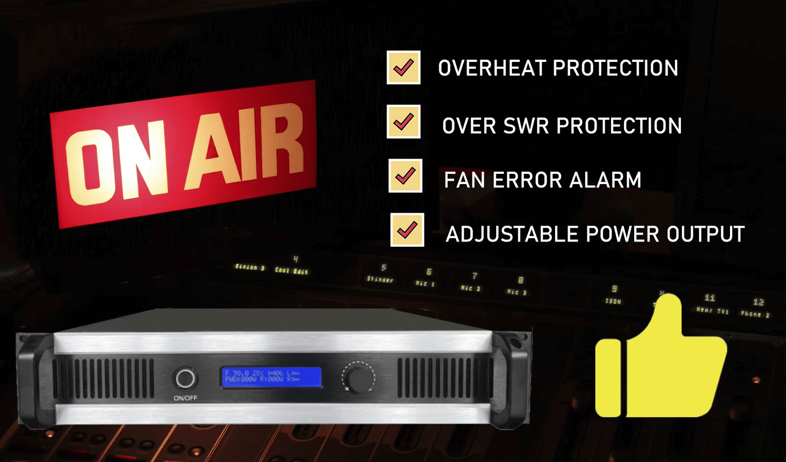
What You’ll Notice
The transmitter goes into protection mode regularly—maybe shutting down completely, or reducing power to safe level, or displaying fault codes. You might need to reset it daily, multiple times per day, or it recovers automatically but the problem recurs. Protection activations are your transmitter’s alarm system saying "something is wrong—fix me before I’m damaged."
Technical Causes
Over-Temperature Protection Activation:
- Cooling system inadequate (see Warning Sign #3)
- Blocked airflow or failed fans
- High ambient temperature
- Component aging increases heat generation
High SWR Protection:
- Antenna system fault (see Warning Sign #4)
- Lightning damage
- Water in coaxial cable or connectors
- Antenna disconnected or damaged
Over-Current/Over-Voltage Protection:
- Power supply failing or irregular
- Failed voltage regulator
- Incoming AC power problems (voltage sags/surges)
- Component short circuit
Interlock or Safety Circuit Activation:
- Cabinet door interlock switch problem
- Missing or damaged RF compartment shield
- Incorrectly installed components after previous service
- False sensor readings
What You Can Check Yourself
-
Identify the specific protection:
- Check transmitter display for fault codes or messages
- Note exactly what triggers shutdown (immediate on power-up, after warmup, during high modulation)
- Record fault type from manual
-
Check obvious causes:
- Over-temperature: Clean dust, verify fans working
- High SWR: Inspect antenna connections (see Warning Sign #4)
- Power supply: Check AC input voltage with multimeter
- Interlock: Verify all covers and shields properly installed
-
Test under controlled conditions:
- Reduce transmitter power 50% and observe if problem persists
- Operate during cooler part of day to eliminate temperature factor
- Try with dummy load to eliminate antenna system
-
Pattern recognition:
- Shuts down after same warm-up time: thermal problem
- Trips during high modulation: power supply or output stage
- Random shutdowns: intermittent connection or sensor fault
- Immediate shutdown on power-up: serious internal fault
When You Need Professional Service
- Protection activates multiple times per week
- Cannot identify cause after basic checks
- Problem returns after attempting fixes
- Multiple different protection types activating
- Transmitter won’t stay running even at reduced power
- No obvious cause (fans working, temperatures normal, SWR good, power stable)
Professional Repair Needed:
- Component-level diagnosis requires test equipment and schematics
- Power supply testing and repair
- Output stage component replacement
- Sensor calibration or replacement
- Thermal analysis and cooling system upgrade
Risk if Ignored: DO NOT IGNORE THIS WARNING. Protection circuits prevent catastrophic damage. Repeatedly resetting without fixing underlying cause stresses components until they fail permanently. A $200 service call now prevents $1500 transmitter replacement. Continued operation against protection warnings can create fire hazard or complete transmitter destruction.
Early Warning Sign #6: Unusual Odors, Sounds, or Visible Component Damage
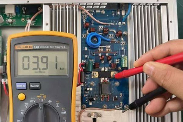
What You’ll Notice
You smell something wrong—burnt electronics, hot plastic, ozone smell near transmitter. Or you hear buzzing, crackling, arcing sounds, or relays clicking repeatedly. Or visual inspection reveals bulging capacitors, scorched circuit boards, melted insulation, or burnt components. These are emergency warning signs requiring immediate action.
Technical Causes and Specific Indicators
Burning Smell:
- Electronics burning: Sharp, acrid odor from overheated resistors, failed transistors, burnt circuit board traces
- Hot plastic: Melting insulation from overheating connections or components
- Ozone smell: Corona discharge from high voltage arcing (sharp, metallic odor)
Abnormal Sounds:
- Crackling/popping: Arcing connections, failing capacitors, poor solder joints
- Buzzing/humming: Loose transformer laminations, failing filter capacitors, corona discharge
- Relay clicking: Power supply voltage fluctuation, protection circuit oscillating, control circuit malfunction
- High-pitched whine: Failing switching power supply, aging electrolytic capacitors
Visual Damage Signs:
- Bulging capacitors: Electrolytic capacitors with domed tops (should be flat)—imminent failure
- Scorched boards: Brown or black discoloration around components
- Melted components: Plastic parts deformed from heat
- Cracked solder joints: Visible cracks or gaps in solder connections
- Burnt resistors: Color bands obscured by black carbon deposits
- Lifted traces: Circuit board traces separated from board
What You Can Check Yourself
SAFETY FIRST:
- If you smell burning or see smoke: IMMEDIATELY POWER OFF AND UNPLUG
- Do not operate transmitter with visible damage
- Do not touch internal components without proper electrical safety training
- High voltage present even after power-off in some circuits
Safe Visual Inspection:
- Power off and unplug transmitter
- Allow 10+ minutes for internal voltages to dissipate
- Remove cover (if manufacturer allows)
- Use flashlight to inspect:
- Look for obviously burnt, scorched, or melted components
- Check for bulging capacitors
- Sniff for burnt smell location
- Photograph any damage for technician reference
- Do not touch circuit boards or components
- Replace cover and call professional service
When You Need Professional Service
IMMEDIATE Professional Service Required:
- Any burning smell (even if transmitter seems to work)
- Any visible component damage
- Any arcing sounds
- Bulging or leaking capacitors
- Scorched circuit boards
- Smoke or signs of fire
Why This Is Urgent: These symptoms indicate components operating outside safe limits or already failed. Continued operation risks:
- Fire hazard (overheating components can ignite)
- Cascading failures (one failed component damages others)
- Complete transmitter destruction
- Safety risk to personnel
- Facility damage
Professional Repair Process:
- Complete internal inspection with power off
- Component-level diagnosis with test equipment
- Replacement of failed and stressed components
- Thermal imaging to identify hot spots
- Safety testing before returning to service
Risk if Ignored: CRITICAL SAFETY RISK. Failed components can cause fire. At minimum, transmitter will fail completely, requiring replacement versus repair. Never ignore burning smells or visible damage.
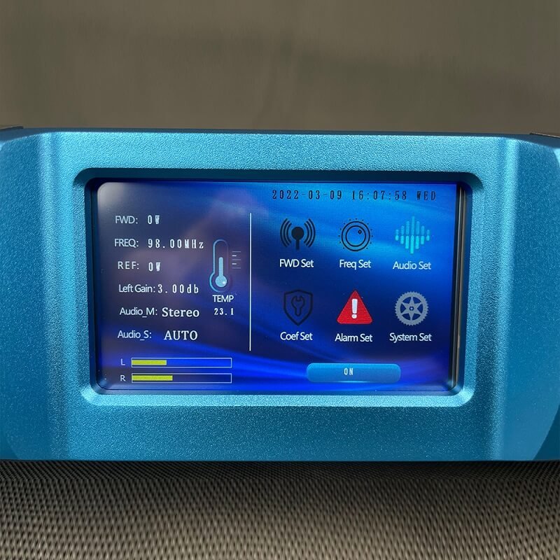
Early Warning Sign #7: Frequency Drift or Modulation Parameters Requiring Constant Adjustment
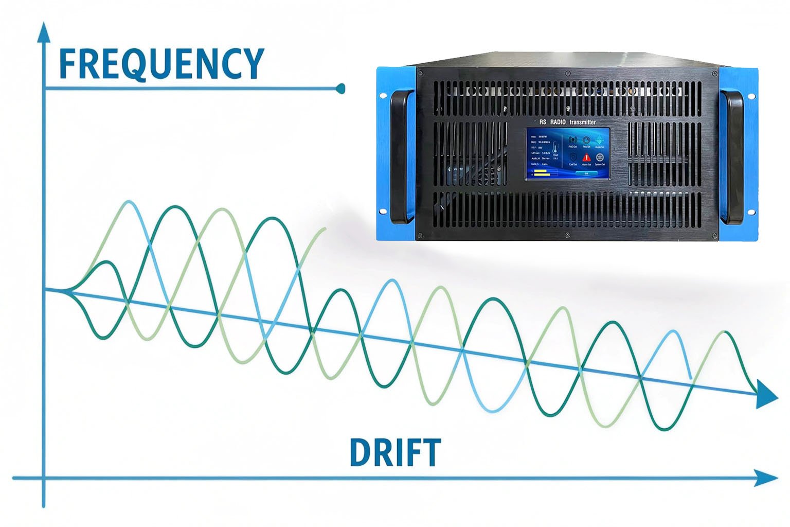
What You’ll Notice
Your transmitter frequency needs retuning more often than it used to. Or modulation depth settings drift, requiring readjustment to maintain proper deviation. Or stereo pilot tone level changes over time. Parameters that should remain stable for months now need tweaking weekly or daily. This indicates aging or failing reference circuits.
Technical Causes
Frequency Stability Problems:
- Crystal oscillator aging: Reference crystal frequency changes slightly over time (normal aging is 1-2 ppm/year, excessive drift indicates problem)
- Temperature-dependent drift: Poor crystal oven control or aging components in temperature compensation circuit
- Voltage reference degradation: Unstable reference voltage affects oscillator frequency
- Component tolerance shifts: Capacitors and inductors in frequency-determining circuits change value
Modulation Circuit Drift:
- Aging varactor diodes: Non-linear response changes over time
- Audio circuit component shifts: Coupling capacitors change value, affecting frequency response
- Pre-emphasis network drift: Changed component values alter pre-emphasis curve
- Modulation limiter threshold shift: Limiting occurs at wrong level
Stereo Encoder Issues:
- 19 kHz pilot oscillator drift: Affects stereo decoder lock
- L-R channel gain variation: Stereo separation changes
- Phase shifter aging: Stereo image shifts
Root Causes of Drift:
- Normal aging (all components drift slightly)
- Temperature cycling stress
- Operating at edge of specification (high power, poor cooling)
- Low-quality components in critical circuits
- Previous repair using incorrect replacement parts
What You Can Check Yourself
Limited User Checks (Most require test equipment):
-
Document the drift pattern:
- Note how often readjustment needed
- Record whether drift is always same direction or random
- Check if drift worse when first powered on (thermal drift)
- Measure time between adjustments (getting shorter indicates accelerating problem)
-
Temperature correlation test:
- If you can safely measure transmitter internal temperature (some have built-in thermometer):
- Note if frequency/modulation stable after warmup
- Drift during warmup indicates thermal stability issue
-
Basic frequency check:
- Use quality FM receiver with digital frequency display
- Compare displayed frequency to licensed frequency
- Drift >±500 Hz from assigned frequency is concerning
- ±1-2 kHz is serious problem requiring immediate service
When You Need Professional Service
Requires Professional Diagnosis and Service:
- Frequency drift exceeds ±500 Hz from assigned frequency
- Modulation parameters need readjustment more than once per month
- Drift accelerating (adjustments needed more frequently)
- Stereo performance degrading
- You lack proper test equipment:
- Frequency counter (measures exact frequency)
- Modulation monitor (measures deviation, stereo parameters)
- Audio analyzer (measures frequency response, distortion)
- Spectrum analyzer (verifies spectral purity)
Professional Service Includes:
- Precision frequency measurement and adjustment
- Crystal oscillator testing and possible replacement
- Modulation calibration with certified test equipment
- Stereo encoder alignment
- Component-level diagnosis of drift sources
- Replacement of aging critical components
- Temperature stability testing
Regulatory Risk: Frequency drift is regulatory violation. FCC rules (USA) and international regulations require transmitters maintain assigned frequency within tight tolerance (typically ±2000 Hz for FM broadcast). Excessive drift causes:
- Interference with adjacent channels
- FCC fines or license sanctions
- Listener complaints about adjacent channel interference
- Legal liability if interfering with emergency services or aviation frequencies
Risk if Ignored: Frequency violations can result in license revocation, substantial fines ($10,000+ in USA), and legal liability. Equipment continues degrading until frequency or modulation so far off-spec that transmission is unusable. Component failure in frequency-determining circuits can cause sudden large frequency shift, creating immediate interference.
When to Call for Professional Service: Decision Framework
Not every problem requires immediate professional help, but some do. Use this framework:
DIY-Appropriate Issues
You can likely handle yourself (with basic technical skills):
- Dust cleaning and basic maintenance
- Checking and tightening connections
- Replacing failed cooling fans (if comfortable with electronics)
- Basic audio cable troubleshooting
- Antenna visual inspection
- Documentation and monitoring
Schedule Non-Emergency Service
Call for service within 1-2 weeks when you notice:
- Gradual coverage reduction (<20%)
- Slight audio quality degradation
- Minor temperature increase (5-10°C above normal)
- SWR slowly increasing (1.3:1 to 1.8:1)
- Occasional protection activations (weekly)
- Minor frequency drift (<1 kHz)
Emergency Service Required
Call immediately or power off until serviced:
- Burning smell or visible smoke
- Sounds of arcing or components failing
- Visible component damage (bulging capacitors, scorched boards)
- Frequent protection shutdowns (multiple times daily)
- Coverage loss >30%
- SWR >2.5:1
- Transmitter won’t stay running
- Frequency drift >2 kHz
- Safety concerns (hot chassis, electrical shock, fire risk)